

Keep one chip exit open, aim air or coolant across the active flute, and retract before chips cover the re-entry path. Packed flutes require a cutter, lubrication, axial-depth, or chip-load correction. Clean flutes above a chip-filled cavity require a better nozzle direction, wider outlet, different fixture angle, or earlier clearing retract.
Check Where the Chips Stop
Stop the machine safely and inspect the cutter, cavity floor, corners, and outlet before changing the feed.
| What You Find | Most Likely Cause | First Action |
|---|---|---|
| Chips compressed inside the flutes | Small flute space, excessive axial depth, built-up edge, or a worn cutter | Inspect the cutter and reduce flute loading |
| Flutes are clean but the cavity floor is covered | Chips leave the cutter but cannot leave the cavity | Correct the air, coolant, gravity, or toolpath exit |
| Chips rotate around the cavity | Opposing nozzles or circular fluid flow | Aim all streams toward one outlet |
| Packing starts at the same depth | The holder or cavity wall blocks the nozzle | Check the jet at the lowest cutting position |
| Load rises only in internal corners | Radial engagement or remaining stock increases | Check the CAM stock model and corner path |
| The tool breaks during re-entry | The entry route crosses a chip pile or hidden stock | Use a cleared and verified entry route |
| The first parts run well but later parts fail | Filter restriction, falling coolant level, nozzle movement, or conveyor loading | Inspect the complete system after several cycles |
Record the exact cavity depth and program position where the load, sound, or chip pattern changes. A problem that starts only near the bottom usually comes from blocked nozzle access or a longer chip escape path. A problem limited to one corner usually comes from increased cutter engagement.
Calculate How Fast the Cavity Fills
Material removal rate = axial depth of cut × radial width of cut × table feed
| Axial Depth | Radial Width | Table Feed | Solid Material Removed |
|---|---|---|---|
| 5 mm | 1 mm | 1,000 mm/min | 5,000 mm³/min, or 5 cm³/min |
| 10 mm | 1 mm | 1,000 mm/min | 10,000 mm³/min, or 10 cm³/min |
| 20 mm | 1 mm | 1,000 mm/min | 20,000 mm³/min, or 20 cm³/min |
At 10 cm³/min, a 15-minute roughing section removes 150 cm³ of solid material. Loose curled chips occupy more space because of the gaps between them. A machine may have enough spindle power for the cut while the cutter flutes and cavity outlet lack enough space to remove the chips.
When the axial depth doubles from 10 mm to 20 mm, the chip volume also doubles if radial width and feed remain unchanged. Check evacuation capacity whenever axial depth, radial width, or feed is increased.
Keep One Exit Open
Open pocket: Rough from the closed area toward the open side when possible. Keep the opening wide enough for curled chips and coolant to pass. Do not leave a narrow full-depth slot as the only outlet.
Blind cavity: Clear the center first and expand the cut outward. Use the cleared center for chip collection, retracts, and re-entry.
Narrow rib slot: The cutter may occupy most of the available width. Reduce chip volume per pass, use enough flute space, and consider through-tool air or coolant when external nozzles cannot reach the cutting edge.
Deep corner: Check the stock left by the previous cutter. An incorrect previous-tool diameter, corner radius, or stock model can leave a much heavier cut for the next tool.
Clamps, supports, fixture walls, and temporary stops must stay outside the chip route. A clamp placed below the cavity opening can collect chips until the pile reaches the cutter.
A WJ-800 horizontal machining center can place an open cavity on its side so gravity helps chips fall away. The fixture must still leave the lower side open.
A safe 3+2 position on a GZXC-2000 five-axis machining center can place the opening below or beside the cutter. Check the holder, spindle nose, clamps, rotary travel, coolant drainage, and the new lowest point before running the program.
Aim Air Across the Flute
Point the air across the active flute and toward the outlet. Do not point it straight down into a closed bottom corner.
Nozzle → active flute → cleared area → cavity outlet
The correct nozzle side depends on spindle rotation, cutting direction, tool movement, and cavity shape. There is no fixed rule that air must always come from the left, right, front, or rear.
Two nozzles can work together when one reaches the cutter and the other clears the outlet. Do not aim equal jets at each other. The chips may rotate inside the cavity without leaving it.
Check the jet at maximum depth. A nozzle that reaches the cutting edge at 20 mm may hit only the holder at 60 or 80 mm.
| Example Depth | Jet Position | Load Trend | Chip Condition |
|---|---|---|---|
| 20 mm | Jet reaches the flute | Stable | Chips leave the outlet |
| 50 mm | Jet partly blocked by the holder | Slowly rising | Chips remain on the floor |
| 80 mm | Jet reaches the holder only | Unstable | One bottom corner packs |
The depths above are a diagnosis example, not machine limits. The failure depth depends on tool stickout, holder size, cavity width, and nozzle position.
A spindle-mounted CNC chip blower can clear loose chips during a programmed retract. It cannot correct a worn edge, packed flutes, or a closed outlet.
Run automatic air blast with the machine enclosure closed. Guards must protect operators from rotating parts and flying chips.[1]
For manual cleaning in the United States, OSHA requires compressed air to be below 30 psi and used with effective chip guarding and personal protective equipment.[2] OSHA applies the pressure limit to static or dead-ended nozzle conditions and does not set a universal limit on normal airflow volume.[3]
Check Coolant at Full Depth
Coolant must reach the active edge and then carry released chips toward the outlet. A cavity full of liquid can still have poor chip movement.
- Aim one focused stream at the active flute.
- Keep one main flow direction across the cavity.
- Provide enough flow to move chips over the wall.
- Keep the return path around the fixture open.
- Check the stream at the lowest programmed Z position.
Under the same supply conditions, a small outlet may produce a focused jet with less total flow. A larger outlet may provide more flow with a less focused stream. Pump output, pipe loss, nozzle count, fluid viscosity, passage size, and nozzle distance also affect the result.
Through-spindle or through-tool coolant helps when the holder and cavity walls block external nozzles. It brings fluid close to the edge during deep helical entry, long-reach milling, and small-tool rest machining.
Through-tool coolant does not create an outlet. It may release chips from the flutes and still leave them on the cavity floor.
If tool-tip flow becomes weak, inspect:
- Coolant tank level
- Pump output
- Filter restriction
- Rotary union condition
- Holder and pull-stud compatibility
- Blocked tool passages
- Nozzle movement
- Conveyor loading
Do not rely only on the pressure gauge. A blocked tool passage can leave system pressure high while little coolant reaches the cutting edge.
Metalworking fluids cool and lubricate the cutting area, while fluid maintenance affects tool life and part quality.[4] NIOSH recommends limiting metalworking-fluid aerosols to 0.4 mg/m³ of thoracic particulate mass or 0.5 mg/m³ of total particulate mass as a time-weighted average for up to 10 hours per day during a 40-hour week.[5]
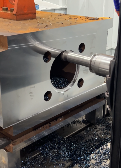
Keep Entry and Exit Clear
Entry: Use helical, ramped, predrilled, or open-side entry when the cutter allows it. Straight plunging with a normal end mill gives chips little escape space. Use it only when the cutter is designed for axial entry.
A helix that is too small keeps too much of the cutter engaged. A helix that is too large may hit the cavity wall or leave unwanted center stock. Use the cutter supplier’s ramp-angle and helix-diameter limits.
Corners: A cutter can run at low radial engagement on a straight section and then meet much more material inside a corner. The feed has not changed, but cutting force and chip volume rise. NIST pocket-milling research shows that tool engagement changes across different parts of a pocket and that cutting conditions may need to change with it.[6]
Check these CAM settings:
- Maximum radial engagement
- Minimum internal path radius
- Previous-tool diameter and corner radius
- Remaining-stock model
- Entry and lead-out moves
- Stay-down distance
- Links between separate cutting areas
A toolpath called adaptive, dynamic, or high efficiency can still create a full-width cut when the rest-stock model is wrong. Check the same points when setting P20 and H13 roughing parameters.
Exit: End the cutting loop inside a cleared area. Do not finish in a deep corner, narrow slot, or chip pile. Move the cutter away from the wall before retracting so loose chips are not dragged across the surface.
Re-entry: Return through the same cleared route. Use rapid movement only above a verified safe area, then enter with a controlled helix, ramp, predrilled hole, or open-side move.
Set Clearing Retracts from Chip Build-Up
Add a clearing retract:
- After an axial level that leaves visible chips
- After a fixed number of roughing loops
- Before entering a narrow rib or corner
- Before changing to a smaller rest-machining tool
- At the depth where the nozzle starts hitting the holder
- Before semi-finishing and finishing
Use this retract sequence:
- Finish the current loop.
- Move into the cleared center or open side.
- Retract high enough to expose the flutes.
- Keep air or coolant running.
- Wait until the re-entry path is clear.
- Return through the same route.
| Trial | Clearing Method | Observed Result |
|---|---|---|
| A | No programmed retract | Chips cover the re-entry route |
| B | Retract after every Z level | Flutes stay clear, but non-cutting time increases |
| C | Retract after every two Z levels | Load stays stable and the route remains clear |
The table is a process-test example. Do not copy the interval without checking the actual cavity. Use the longest interval that still leaves clean flutes and a clear re-entry path.
Remove all roughing chips before finishing. One trapped chip can be thicker than the finishing allowance and cut a groove into the floor or wall. Measure any damaged area against the drawing, using the same approach applied when checking surface roughness and rework limits.
Leave Space Beside the Cutter
Flute count alone does not show whether a cutter can remove chips from a deep cavity. Check:
- Flute cross-sectional area
- Core thickness
- Flute surface finish
- Helix angle
- Chip-splitter geometry
- Internal coolant holes
- Effective cutting length
- Neck clearance
- Cutter diameter compared with the narrowest cavity width
Aluminum cutters often use sharp edges and smooth, open flutes because aluminum produces bulky chips and can stick to rough flute surfaces. A multi-flute cutter can still work when its flute design, engagement, and coolant delivery suit the operation.
Steel chips are denser and can fall back into a blind cavity more easily. Their size depends on feed, engagement, cutter geometry, and chip splitters.
Chip splitters divide a wide chip into narrower pieces. They can improve transport during deep axial roughing, but they cannot solve a blocked outlet.
Do not use a cutter that nearly fills the narrowest part of the cavity. The remaining gap may be too small for chips and coolant to pass.
Match the carbide grade, coating, edge shape, and flute design to the material and cutting method. The main selection points are covered in the mold-steel cutting-tool guide.
Use the Shortest Tool That Reaches
Use a short cutter for the upper cavity, a medium-reach cutter for the middle, and a long-reach cutter only for the deepest section.
Longer overhang changes the vibration and stable-cutting limits of the spindle, holder, and cutter system.[7]
Excessive overhang can cause:
- Tool deflection toward the wall
- Chatter
- Uneven chip thickness
- Poor wall finish
- Faster edge damage
- Changing nozzle access
A rigid machine cannot fully correct an unnecessarily long cutter. Plan tool length, roughing, rest machining, semi-finishing, and finishing together as part of the full mold and die machining process.
Recalculate Feed After Changing the Cutter
Programmed feed per tooth = table feed ÷ spindle speed ÷ number of flutes
| Table Feed | Spindle Speed | Flutes | Programmed Feed per Tooth |
|---|---|---|---|
| 1,200 mm/min | 10,000 rpm | 2 | 0.060 mm/tooth |
| 1,200 mm/min | 10,000 rpm | 3 | 0.040 mm/tooth |
| 1,200 mm/min | 10,000 rpm | 4 | 0.030 mm/tooth |
The table shows the calculation only. It is not a recommended cutting range. Changing from two flutes to four without changing the table feed cuts programmed feed per tooth in half.
At low radial engagement, the actual maximum chip thickness can be lower than the programmed feed per tooth. Do not reduce feed again without checking the cutter supplier’s chip-thinning correction.
A cutting edge also needs enough undeformed chip thickness to form a chip. Below the minimum chip thickness, more material can be pushed or rubbed instead of being removed cleanly, increasing heat and surface damage.[8]
When chip volume is too high:
- Reduce radial engagement when load rises in corners or the tool deflects.
- Reduce axial depth when chips pack along the active flute length.
- Keep feed within the cutter supplier’s approved range.
- Change one setting at a time.
- Repeat the same program section after each change.
Match the Check to the Material
| Material | Main Packing Risk | First Checks |
|---|---|---|
| Aluminum | Bulky chips, built-up edge, and scratched floors | Sharp edge, polished flutes, lubrication, chip thickness, and open outlet |
| Prehardened mold steel | Dense chips falling back into the cavity | Corner engagement, coolant direction, tool overhang, and clearing interval |
| Hardened mold steel | Hard recut chips damaging semi-finishing or finishing edges | Tool condition, approved dry or wet method, and cavity cleaning before finishing |
| Graphite | Conductive dust entering the machine | Enclosed extraction and suitable filtration instead of uncontrolled air blast |
For P20 and H13 work, confirm the supplied hardness before choosing cutting data. Do not copy a feed, speed, or coolant method from a different hardness, cutter diameter, coating, or tool overhang.
Stop Before the Tool Fails
Stop the cycle when:
- Spindle load rises continuously as the cutter moves deeper.
- The cutting sound changes to repeated knocking or grinding.
- Chips wrap around the holder or collet area.
- Air or coolant flow stops.
- The cavity outlet becomes covered.
- A chip pile blocks the re-entry route.
- The cutter retracts with packed flutes.
- The workpiece or fixture starts to vibrate.
- A nozzle moves away from its checked position.
Do not continue only because the spindle load remains below the machine alarm. The cutting edge may already be rubbing, recutting chips, or developing built-up edge.
Before manual cleaning, stop all motion, wait for the cutter to stop, follow the approved energy-control procedure, and use a brush, chip hook, vacuum, or approved cleaning tool. Do not pull sharp chips with bare hands.
Verify the Fix on Repeated Cavities
Record the material, hardness, cavity depth, outlet width, cutter diameter, flute count, stickout, spindle speed, feed, radial width, axial depth, nozzle position, and failure depth.
Clear the cavity, change one item, and repeat the same section of the program. Do not change the cutter, toolpath, feed, speed, depth, nozzle direction, and coolant pressure in one trial.
| Check | First Cavity | Third Cavity | Fifth Cavity |
|---|---|---|---|
| Tool-tip flow | Record the baseline | Compare with the baseline | Check for filter or nozzle change |
| Spindle-load trend | Record by depth | Check repeatability | Check for continuous increase |
| Chip position | Mark the collection area | Check whether the pile grows | Confirm the re-entry route stays clear |
| Flute condition | Check for packed chips | Check for early buildup | Inspect for wear or edge damage |
The first, third, and fifth cavities are a sampling example, not a fixed inspection rule. Check more often when the cycle is long, the cavity is deeper, or coolant flow changes quickly.
Accept the correction only when:
- Spindle load stays stable as depth increases.
- The flutes are open after retracting.
- No chip pile covers the re-entry route.
- The cavity floor has no random recutting scratches.
- Tool-tip flow remains similar after several parts.
- The cutting edge shows repeatable wear instead of sudden chipping.
Finally
Chip packing is a location problem before it is a feed problem. At a 10 mm axial depth, 1 mm radial width, and 1,000 mm/min feed, the cutter already creates 10 cm³ of solid chips each minute; doubling the axial depth doubles that load. Packed flutes need a cutter, lubrication, depth, or chip-load correction. Clean flutes above a full cavity need a better nozzle direction, wider outlet, fixture angle, or retract interval. Check the jet at maximum depth, keep one exit open, clear the cavity before finishing, and compare repeated cavities before approving the process.