

Burrs appear because the metal at the cut edge bends, stretches, tears, or melts before it separates completely. In mechanical cutting, the largest burr often appears where the tool leaves the material. In laser and plasma cutting, the rough deposit under the plate is usually molten metal that was not fully removed from the cut.
A worn tool is only one possible cause. Wrong speed, unsuitable feed, poor support, vibration, bad alignment, incorrect punch clearance, blocked chip flow, or weak cutting-gas flow can create a similar edge. Inspect the defect before grinding it away. Its shape, position, and timing often show what should be checked first.
What Is a Burr?
A burr is unwanted material attached to the edge of a metal part after cutting, drilling, punching, milling, turning, or grinding.
It may look like:
- A thin, sharp lip
- A folded edge
- A rough torn section
- A small point at the end of a cut
- Loose metal inside a hole
- A hard deposit under a thermal cut
A mechanical burr is normally part of the original metal that has bent, stretched, smeared, or torn. Dross and slag are different. They are melted or oxidized material that cooled and attached to the edge after laser, plasma, or oxy-fuel cutting.
Mechanical burrs usually lead back to the cutting tool, feed, clearance, part support, or cutting direction. Thermal dross usually leads back to heat input, gas flow, focus, torch height, travel speed, or worn consumables.
Why Metal Leaves a Burr
A cutting edge first presses into the metal. The material deforms, then begins to shear or fracture. Near the end of the cut, the remaining layer becomes thin and has less support. Instead of being removed cleanly, it may bend away from the tool and tear.
This is why a drill often leaves a burr on the back of a through-hole, a punch normally leaves one on the die side, and a milling cutter often creates one where it exits the workpiece.
A sharp edge cuts through a small area. A worn edge pushes more metal ahead of it, so cutting changes into rubbing, pressing, and smearing. Sandvik Coromant lists a cutting edge that is not sharp enough and feed that is too low for the edge radius among the common causes of turning burrs.[1]
Thermal cutting works differently. A laser, plasma arc, or flame creates a narrow opening called the kerf. Gas must remove molten or oxidized material through the bottom. Material left in the kerf cools into dross or slag.
Entry and Exit Sides
The entry side is where the tool first touches the material. The exit side is where it leaves. Mechanical burrs are often larger at the exit because the last layer of metal has less support.
- A drill usually enters from the top and exits at the bottom.
- A punch enters from the punch side and exits through the die.
- A saw tooth enters one side of the section and leaves the other.
- A milling cutter has entry and exit edges along its path.
- Laser and plasma dross usually appears under the plate.
Use three different tests when checking direction:
- Flip the part: exchange the top and bottom surfaces.
- Rotate the part 180 degrees: keep the same face upward but reverse its position on the table.
- Reverse the cutting path: change the tool or torch travel direction.
Flipping checks the entry and exit faces. Rotating checks whether the defect follows the machine. Reversing the path checks whether it follows the cutting direction.
What the Burr Can Tell You
Burr shape cannot prove one cause, but it can narrow the search.
| What you see | Likely causes | Check first |
|---|---|---|
| Burr becomes larger during production | Tool wear, consumable wear, contamination, heat, or chip buildup | Compare with a confirmed good tool or consumable |
| Burr appears suddenly | Chipped edge, loose fixture, damaged nozzle, or material change | Look for something that changed after the previous good part |
| Burr is larger on one side | Misalignment, exit direction, weak support, warped material, or uneven gas flow | Rotate the part and reverse the cutting path |
| Large burr at the end of the cut | The part moved or dropped before separation was complete | Support the finished section close to the cutoff point |
| Thin, sharp lip | Light tool wear, rubbing, ductile material, or weak exit support | Inspect the edge and confirm that feed is not too low |
| Thick folded edge | Dull tool, excessive force, or excessive punch clearance | Check the tool and cutting setup |
| Hard deposit under a thermal cut | Fast travel, weak gas flow, wrong focus, excessive torch distance, or worn consumables | Check hardware and gas before changing speed |
| Defect mainly at corners | Machine slowdown, extra heat, local tool exit, or weak support | Check corner settings and local support |
Main Causes
Worn tools: A dull blade, drill, punch, insert, or milling cutter pushes material instead of cutting it cleanly. Look for rising machine load, louder cutting noise, rougher surfaces, discolored chips, or repeating marks from a damaged tooth.
A tool may look complete while its edge is already rounded. Keep the material and program unchanged, install a known good tool, and compare the next part. ASIATOOLS explains how carbide grade, coating, geometry, hardness, and machine rigidity affect tool choice in its cutting tool selection guide.
Wrong speed: Mechanical cutting speed and thermal travel speed are different settings. In machining, unsuitable speed can increase rubbing, material adhesion, heat, or edge wear. In thermal cutting, moving too slowly may create a wide kerf and heavy deposits, while moving too quickly may leave incomplete penetration or hard lower-edge dross.
Wrong feed: Feed that is too low may make the edge rub instead of forming a proper chip. Feed that is too high raises cutting force and may bend the tool, move the part, break teeth, or tear the exit edge.
Poor alignment: A punch that is not centered, a tilted torch, a saw blade that is not square, spindle runout, or an off-center laser nozzle can make one side worse than the other.
Weak support: Thin sheet, long bar, tube, and narrow profiles can move during cutting. The part may also drop near the end of a saw or cutoff operation. Place support close to the cut without bending or crushing the workpiece.
Vibration: Loose clamps, long tool overhang, worn bearings, low band-saw tension, damaged holders, and unbalanced abrasive wheels can make the edge repeatedly leave and re-enter the metal. The cut may show waves or repeated chatter marks.
Poor chip removal: Chips trapped around a saw tooth, drill, or milling cutter may be cut again. This raises heat, damages the tool, and scratches the part.
Material Effects
Different metals form different burrs. Material thickness, hardness, surface condition, and heat treatment also change the result.
- Aluminum: often sticks to the cutting edge and produces smearing or folded burrs.
- Mild steel: may form long rollover burrs when the tool is worn or the part is poorly supported.
- Stainless steel: may work-harden when the tool rubs, increasing heat and tool wear.
- Copper: is ductile and may leave a long thin lip or stick to the tool.
- Hardened steel: often leaves small hard projections or fractured edges rather than a long soft lip, but toughness and heat treatment still matter.
Thin sheet bends and vibrates more easily. Thick material gives chips, heat, and molten metal a longer path out of the cut. Rust, scale, paint, oil, protective film, sheet bow, and thickness changes can also affect edge quality.
Sawing
Saw burrs usually appear where the teeth leave the section or where the part finally separates from the stock.
Keep enough teeth in the cut: DoALL recommends that a band-saw blade normally has about 6 to 24 teeth engaged in the workpiece.[6] Too many engaged teeth reduce chip space and increase rubbing. Too few place a high load on each tooth and may cause catching, tooth damage, and a rough exit edge.
This is why thin-wall tube usually needs a finer pitch than a thick solid block. Tooth pitch must be selected from the wall thickness or changing cross-section, not only the outside size of the workpiece.
Break in a new blade: For many bi-metal blades, DoALL recommends reducing feed force to about 50% of the normal rate for roughly 20 minutes, then raising it in steps.[6] Carbide blades may require a different method, so follow the blade maker’s instructions.
Check blade tension: Low band-saw tension can let the blade move sideways, producing an angled surface and an uneven burr.
Check final separation: A heavy part that drops early can tear the last connection. Support it close to the blade without allowing the cut to close and pinch the blade.
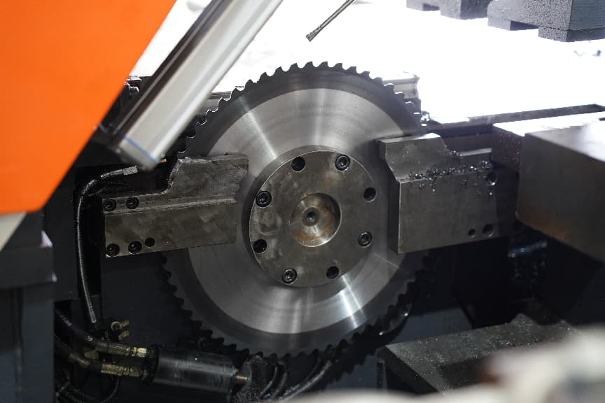
For machine and blade selection, see the ASIATOOLS guides on choosing a circular saw for steel blocks and comparing circular saws with band saws. A production machine example is the PCS-1000NC flat-plate circular saw.
Abrasive Cutting
Angle grinders and abrasive cutoff saws remove material with abrasive grains. Their edges may show a sharp lip, heat discoloration, and abrasive residue at the same time.
Common causes include:
- A worn or glazed disc
- A disc that is not suitable for the metal
- Side pressure on a thin cutoff wheel
- Changing the cutting angle during the cut
- Poor clamping
- Forcing the wheel through the material
A thin cutoff wheel is made mainly for straight radial cutting. Side loading can damage it and widen the cut. OSHA advises using the correct guard, keeping machine speed below the wheel’s rated speed, and following the wheel maker’s instructions.[2]
Punching and Shearing
A punched edge normally has four visible areas: a small rollover at the entry, a smoother cut area, a rough fracture area, and a burr at the exit.
The total punch-to-die clearance is normally set as a percentage of sheet thickness. AMADA gives the following reference ranges:[7]
| Press type | Mild steel | Aluminum | Stainless steel |
|---|---|---|---|
| Mechanical or hydraulic press | 12%–18% of sheet thickness | 10%–16% | 14%–22% |
| Servo press | 20%–25% | 15%–20% | 25%–30% |
For example, a 2 mm mild-steel sheet gives a total reference clearance of about 0.24–0.36 mm on a mechanical or hydraulic press. On the AMADA servo-press range, the same sheet gives about 0.40–0.50 mm. These are starting references, not universal settings. Tool design, part requirements, material hardness, and the machine manual still control the final value.
Too much clearance lets the sheet bend and stretch before breaking, producing more rollover and a longer burr. Too little clearance raises force, increases tool wear, and may produce a second shear mark.
For shearing, a suitable clearance often produces a smooth sheared area measuring roughly one-third to one-half of the sheet thickness before the fractured area begins.[8] A very large fractured area with heavy rollover and burr suggests that the clearance may be excessive.
If the burr becomes larger gradually, inspect punch and die wear. If it becomes large suddenly on one side, check for a chipped edge, loose tool, poor alignment, or a change in sheet thickness.
In punching, the hole is the required feature and the removed slug is scrap. In blanking, the removed outside shape is the required part. The burr direction on the useful part is therefore different.
Drilling
A through-hole usually has its largest burr on the side where the drill exits. As the drill breaks through, the last thin layer bends under the drill force.
Check:
- Drill sharpness
- Drill-point geometry
- Feed near breakthrough
- Tool runout
- Support under the exit face
- Chip removal
- Material stuck to the drill
A backing plate, a sharper drill, a suitable point shape, or controlled breakthrough feed may reduce the burr. Do not reduce feed so far that the drill begins rubbing.
A blind hole has no normal exit burr, but it may still have a raised entrance edge or chips at the bottom. Cross-drilled holes can leave hidden burrs where two passages meet. These loose pieces are a serious problem in hydraulic, cooling, fuel, and lubrication systems.
For deep and intersecting holes, see the ASIATOOLS guide to machining guide-pin, ejector-pin, and cooling holes.
Milling and Turning
Milling burrs usually form where the cutter leaves the workpiece. Their position changes with tool rotation, feed direction, cutting path, part shape, and the amount of material left for the final pass.
Check insert condition, runout, tool overhang, clamping, feed per tooth, and chip recutting. One damaged insert may leave a repeating mark around the part.
Changing the path may move the burr from a critical surface to an edge that is easier to finish. Stable blank preparation also helps the final machining stage. ASIATOOLS discusses this in its guide on using a duplex milling machine for blank preparation.
Turning burrs often appear at shoulders, grooves, end faces, and cutoff points. A cutting edge that is too blunt or a feed that is too low can produce an exit burr.[1]
During parting, the final center may break before the tool reaches the exact axis. This leaves a small point, often called a cutoff pip. Tool center height, insert shape, feed, edge sharpness, and support for the finished part affect its size.
Laser Cutting
Laser dross forms when molten material is not fully pushed out before it cools. Do not start by changing several program settings.
Check in this order:
- Confirm the material and thickness.
- Inspect the nozzle for damage and dirt.
- Check nozzle centering.
- Inspect the protective optical component.
- Check nozzle height and sheet flatness.
- Confirm that cutting-gas supply is stable.
- Then test focus, speed, and power one setting at a time.
TRUMPF states that correct nozzle geometry and stable gas flow help reduce burr formation.[3] A damaged or off-center nozzle may produce one-sided dross even when the programmed speed is correct.
Oxygen, nitrogen, and compressed air do not produce identical results. Oxygen supports a cutting reaction in suitable carbon-steel applications. Nitrogen mainly uses pressure to remove molten metal and limit oxidation. Avoid using one gas-pressure or focus value for all materials.
Dross around corners often appears because the cutting head slows while heat input remains high. Check corner power, acceleration, small-hole settings, lead-in position, and pauses in the path.
Plasma Cutting
Plasma dross depends on travel speed, current, torch distance, consumables, gas, material type, thickness, and surface condition.
Low-speed dross is usually thick, rounded, and easier to remove. After checking the nozzle, current, and torch distance, increase travel speed in small steps.
High-speed dross is usually a narrow, hard bead under the plate. The arc trails behind because the torch is moving too quickly. Worn nozzles, low current, or excessive torch distance can produce a similar result. Hypertherm recommends checking nozzle wear before reducing speed.[4]
On Hypertherm troubleshooting guidance, low-speed dross tests may use travel-speed changes of 5 in/min, equal to about 127 mm/min, at a time.[4] Some Hypertherm systems also use torch-height changes of about 1/16 in, or roughly 1.6 mm, or arc-voltage changes of 5 V or less during controlled testing.[9]
Top spatter is re-solidified metal on the upper edge. A worn nozzle, excessive torch distance, poor piercing settings, and incorrect travel speed can all contribute. Check the approved cut chart rather than assuming that speed must always be changed in one direction.
The two sides of a plasma kerf may not have the same angle. Torch-gas rotation and cutting direction affect which edge is straighter. Follow the direction shown in the machine maker’s cut chart rather than using one rule for every system.
Oxy-Fuel and Waterjet
Oxy-fuel slag may come from wrong travel speed, a dirty cutting tip, incorrect oxygen supply, wrong tip size, poor torch height, weak preheat, or heavy rust and scale.
Conventional oxy-fuel cutting mainly suits steels that support the required oxidation reaction. Aluminum, copper, and stainless steel should not be treated like ordinary carbon steel.
Waterjet cutting may leave a small edge projection, but its more common defects are kerf taper, stream lag, and rough lines near the lower edge. A worn mixing tube, excessive travel speed, poor abrasive flow, wrong standoff, or poor piercing can cause these problems. Diagnose the edge before calling every rough area a burr.
How to Troubleshoot
Use the same order each time. Random adjustments waste material and hide the cause.
- Decide whether the defect is a mechanical burr, dross, slag, taper, or simple roughness.
- Mark the top, bottom, entry, exit, feed direction, and machine direction.
- Confirm material, thickness, flatness, coating, and surface condition.
- Inspect the blade, drill, insert, punch, nozzle, optical part, or plasma consumable.
- Check clamps, support, guides, blade tension, and tool overhang.
- Check alignment, runout, nozzle centering, and torch angle.
- Confirm coolant, gas, air, oxygen, or abrasive supply.
- Change only one setting and cut another test part.
Record at least five details: material and thickness, tool or consumable, defect location, cutting direction, and the part count when the problem appeared. Also record the original setting, changed setting, and result. A short record is more useful than relying on memory between shifts.
Burrs on rough-cut blanks can affect later clamping and machining. The ASIATOOLS guide to preparing steel blocks before CNC machining explains why cut quality, squareness, and clean datum surfaces matter before the blank reaches the next machine.
How Much Burr Is Acceptable?
There is no universal acceptable burr height. The limit depends on the drawing, handling risk, assembly, coating, cleanliness, and service conditions.
A burr needs attention when it:
- Can cut a worker or customer
- Stops two parts from sitting flat
- Changes a measured dimension
- Damages a seal, cable, hose, bearing, or thread
- Can break loose inside the product
- Interferes with paint, plating, or powder coating
- Exceeds the edge condition shown on the drawing
“Deburr,” “break sharp edges,” and “machine a chamfer” are not the same instruction. Deburring removes unwanted projecting material. Breaking an edge removes sharpness. A chamfer or radius is a measured feature.
ISO 13715 provides rules for showing and dimensioning edges of undefined shape. A defined chamfer, such as a stated size and angle, should be treated as a controlled part feature rather than general deburring.[5]
Deburring Methods
Fix the cutting cause before adding more finishing work. When edge treatment is still required, choose a method that does not damage the part.
- Files and scrapers: useful for prototypes and low-volume work, but results depend on the operator.
- Abrasive belts and brushes: fast on accessible edges, but may round corners or remove coatings.
- Countersinks and chamfer cutters: create a controlled hole or edge finish when the drawing allows it.
- Tumbling: processes many small parts together, but can affect threads, holes, thin walls, and surface finish.
Deburring can create another burr. A scraper may fold a thin lip to the other side. A countersink may leave a small edge inside the hole. A chamfer cutter may create a new exit burr. Inspect both sides after finishing.
For larger and repeated edge-finishing jobs, see the ASIATOOLS guide on CNC chamfering and burr removal. The DJX3-1000-600S CNC chamfering machine is one equipment example for mold-steel and aluminum workpieces.
Safety
Do not run a bare finger along a freshly cut edge. Use visual inspection, magnification, an edge gauge, or another controlled method.
- Clamp the workpiece before cutting or deburring.
- Keep machine and grinder guards installed.
- Check that abrasive discs are rated for the machine speed.
- Wear suitable eye and face protection.
- Keep hands away from rotating tools.
- Remove loose clothing and jewelry.
- Control hot chips, sparks, fumes, and dust.
- Follow the machine, tool, and consumable maker’s instructions.
Fine combustible metal dust can create fire or explosion risks when it collects and finds an ignition source. Do not use an unsuitable vacuum or mix reactive metal dusts without an approved collection method.
Conclusion
Most burr problems can be narrowed down with five records: material and thickness, tool or consumable, defect location, cutting direction, and the part count when the defect appeared. In band sawing, aim for about 6–24 teeth in the cut. In punching, total clearance may range from roughly 10% to 30% of sheet thickness depending on material and press type. For plasma testing, make small changes rather than large jumps. Check the hardware first, change one setting, and compare the next part. This prevents unnecessary grinding and makes the correction repeatable.
Technical Sources
- Sandvik Coromant: Troubleshooting in Turning
- OSHA: Safe Use of Portable and Hand-Held Power Tools
- TRUMPF: Laser Cutting Nozzles and Gas Flow
- Hypertherm: Troubleshooting Excess Plasma Dross
- ISO 13715:2017 — Edges of Undefined Shape
- DoALL: Band-Saw Blade FAQ
- AMADA: Punching Basics and Die Clearance
- AMADA: Shearing Clearance and Cut-Edge Shape
- Hypertherm: Powermax SYNC Troubleshooting Reference