

when a circular saw starts cutting mold steel out of square, the problem usually comes from one of five places: the blade is not running true, the blade is bending under load, the workpiece is moving, the guide or saw head has play, or the steel itself is moving as internal stress is released.
On thick stock, it does not take much error to become visible. If the bottom of a 100 mm-deep cut is 0.5 mm off from the top, that is only about 0.29°. At 1.0 mm of error, the angle is still only about 0.57°. So a saw can look “almost perfectly square” and still leave a mold block that needs a noticeable amount of cleanup.
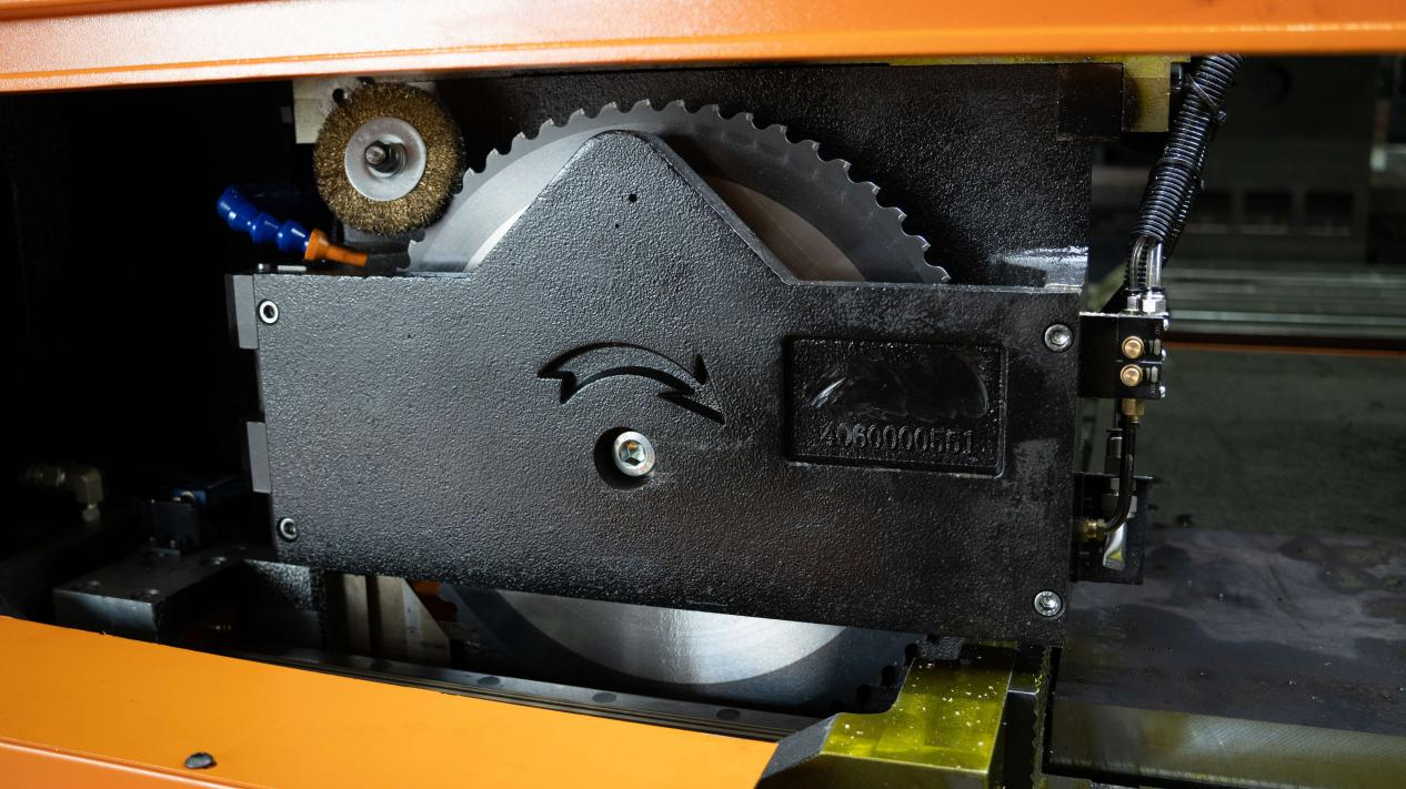
The mistake I would avoid first is adjusting the fence before knowing what actually moved. A fence cannot correct a dirty flange, a bent blade, spindle play, poor clamping, or a kerf that is closing on the blade.
Start With the Cut
The cut face usually tells you where to look.
If the whole face is flat but leans at the same angle from top to bottom, start with fixed geometry: blade angle, fence, guide, spindle position, or saw-head alignment.
If the top looks right but the cut slowly moves sideways as it gets deeper, that is a different problem. Now blade deflection, cutting load, tooth condition, bearing play, or movement in the guide or saw head becomes more likely.
A curved face is an especially useful clue. A fixed alignment error tends to produce a straight face at the wrong angle. A blade that is being pushed sideways tends to leave a cut that bends as it goes deeper.
If one part cuts left and the next one cuts right, I would look at the workholding before touching the machine alignment. Chips under the block, uneven support, clamp movement, or stress inside the steel can all make the result change from cut to cut.
And if almost the whole cut looks good except for the final few millimeters, check the offcut. A heavy offcut can drop or twist just before separation and spoil the exit side of an otherwise good cut.
Small Errors Get Bigger in Thick Steel
One reason this problem shows up so clearly on mold steel is simple geometry. The deeper the section, the more visible a small angle error becomes.
| Cut Depth | Top-to-Bottom Error | Approx. Angle Error |
|---|---|---|
| 50 mm | 0.10 mm | 0.11° |
| 50 mm | 0.20 mm | 0.23° |
| 100 mm | 0.50 mm | 0.29° |
| 100 mm | 1.00 mm | 0.57° |
These are not tolerance limits. They are only there to show how little angular error is needed to create a measurable difference on a deep cut.
Make Sure the Measurement Is Real
Before blaming the saw, make sure the face you are using as a reference is actually usable.
This matters more than people think with rough mold-steel blanks. A block may have a burr, mill scale, a rough flame-cut edge, a dent, or a face that was never truly square in the first place.
Put a machinist square against a bad reference and the measurement is bad too.
Clean the surfaces first. Remove burrs and loose scale. If accuracy matters, measure from a known flat face rather than an unfinished forged or flame-cut surface.
Blade Runout
Runout means the blade does not stay in exactly the same plane as it turns.
On thin material, a small amount of sideways movement may only make the kerf wider. On a deep block of mold steel, it can create rubbing, vibration, uneven tooth load, and eventually an angled cut.
The blade itself may be the problem, but not always. Runout can come from the blade body, the bore, dirty flanges, a damaged arbor, spindle error, worn bearings, or simply poor blade seating.
A new blade mounted against one hard chip on the flange can run worse than an old blade mounted correctly.
Measure Runout Properly
With the machine isolated from power, put a dial indicator against a flat part of the blade body. Stay away from teeth, expansion slots, stamped areas, and damaged sections.
Turn the blade slowly by hand through one full revolution and watch the highest and lowest readings.
If the indicator goes from 0.02 mm to 0.10 mm, the total movement is:
0.10 mm − 0.02 mm = 0.08 mm TIR
TIR means total indicator reading. The number tells you how much movement you measured; it does not tell you by itself whether the blade is acceptable. There is no single runout limit that fits every blade diameter and every machine.
A useful next step is to mark the blade at the high point. If the machine design allows it, remove the blade, rotate its mounting position on the arbor, reinstall it, and measure again.
- If the high point moves with the blade, look harder at the blade or its seating.
- If the high point stays in roughly the same place on the machine, check the flange, arbor, spindle, and bearings.
That simple test often saves a lot of unnecessary part swapping.
Flanges, Arbor, and Bearings
The blade needs clean, flat mounting surfaces. A tiny steel chip trapped behind the blade is enough to tilt it.
Check the flanges for metal particles, rust, burrs, dents, or damage around the arbor hole. Clean them carefully. Do not grind a precision flange unless the machine manufacturer specifically allows that repair.
The arbor deserves its own check as well. Radial runout is movement on a rotating cylindrical surface. Face, or axial, runout is wobble on a face that should rotate square to the axis. That is not the same thing as axial endplay, where the spindle itself moves in and out because of bearing clearance.
Bearings can be tricky because the saw may look fine while stopped. Once the blade enters solid steel and the load comes up, a worn spindle can move.
Repeated runout readings that do not match, unusual spindle noise, visible looseness, or the same bad cut with several known-good blades all point toward the machine rather than the blade.
Blade Deflection
Runout and deflection are easy to mix up.
Runout is there while the blade rotates. Deflection happens only when cutting force pushes the blade away from its normal plane.
That means a blade can measure perfectly well with a dial indicator and still cut crooked in a thick block.
Deflection becomes more likely when the cutting edges are dull, feed pressure is high, the section is deep and solid, chip removal is poor, the blade is too flexible for the job, or the machine structure itself moves under load.
This is also why maximum cutting capacity should not be confused with maximum accuracy. A machine that can physically get through a 100 mm section may not hold the same squareness there that it holds on a 20 mm section.
Check the Teeth
A blade does not have to be completely worn out before the cut starts drifting.
Look for dull edges, chipped teeth, missing tips, uneven tooth height, uneven wear, and material stuck to the cutting edges.
Industrial steel cutting does not use only one blade type. Depending on the machine and application, you may see HSS, TCT, or segmental circular saw blades.
Resharpening can also create problems. If tooth height, side clearance, or cutting-edge shape is not restored evenly, cutting force can become unbalanced across the blade.
If the saw was cutting square, the blade went out for sharpening, and the problem started immediately after that blade came back, check the blade before you start moving the fence.
Some cold-saw manufacturers also recommend a gentler feed during the first few cuts with a new or resharpened blade. Use the procedure for the actual blade and machine rather than applying one break-in rule to everything.
Watch for Pick-Up
Pick-up is easy to miss. It happens when steel sticks to a tooth or cutting edge and makes that spot wider than it should be.
Once that happens, the blade can start rubbing or grabbing the workpiece. The result may look like runout, tooth damage, or poor alignment.
Common causes include a dull blade, the wrong blade, incorrect speed, poor lubrication on machines that need it, excessive feed, or poor chip removal.
A repeating clunk, sudden vibration, heavy rubbing on one side, or the workpiece moving in the vise are all worth checking.
If buildup is severe enough to make the blade grab or bind, stop and deal with it. Do not keep cutting and hope it clears itself.
Mold Steel Is Not One Cutting Condition
This is where mold steel gets interesting. Two blocks can look almost identical and put very different loads on the saw.
For example, 1.2312 / P20+S may be supplied around 29–34 HRC. H13-type tooling is commonly used around the mid-40s to roughly 50 HRC in many applications.
That difference is large enough that the same blade, speed, and feed should not automatically be expected to work the same way on both.
| Example Material Condition | Typical Hardness | What It Means for the Cut |
|---|---|---|
| 1.2312 / P20+S, prehardened | About 29–34 HRC | Generally lower cutting load than harder tool-steel conditions |
| H13-type tooling | Often about 45–50 HRC in many applications | Higher tooth load and faster wear if the blade or cutting data are not suitable |
Before troubleshooting the machine, confirm the steel grade, actual hardness, heat-treatment condition, section size, and surface condition.
The grade name alone is not enough. The same steel can behave very differently in annealed, prehardened, and fully hardened conditions.
Local Hard Areas
Average hardness can also hide a local problem.
A flame-cut heat-affected zone, nitrided surface, weld repair, or locally heat-treated edge may be much harder than the surrounding material.
If the blade behaves normally through most of the block and starts drifting near one edge, do not immediately assume the guide suddenly moved. Check the material too.
Mill scale is a separate issue. It does not automatically mean the steel underneath is hardened, but it can be abrasive and can interfere with workpiece seating.
Residual Stress
Sometimes the machine is stable, the clamps are tight, and the block still moves.
Steel can carry residual stress from rolling, forging, heat treatment, flame cutting, or previous machining. Once the saw starts removing material, that stress can redistribute.
The kerf may open. Or it may close.
If it closes, the workpiece starts squeezing the blade. Motor load goes up, rubbing increases, and the blade may begin to drift.
This is one reason a cut can start normally and become much harder halfway through.
Residual stress is not the only cause of a closing kerf. Poor support, workpiece weight, or clamp position can create a similar effect. The useful clue is that the workpiece itself is changing shape or position while the cut is being made.
If only one block or one batch behaves badly while other material cuts normally on the same setup, that is a strong reason to look at the steel before realigning the machine.
Clamping and Support
A mold block can weigh a lot and still move enough to spoil a cut.
Start with the basics: clean the bed, fence, and workpiece contact surfaces. A small chip under a large block can tilt the whole part.
Then watch what happens when the clamp is applied. The clamp itself may push the block away from the fence, rotate it slightly, or pull one side down before the other.
If you have a dial indicator available, put it against the workpiece and watch the reading while the clamps are tightened. If the part moves before cutting starts, the problem is already there.
Clamp position matters too. The farther the clamp is from the cutting zone, the easier it is for the material to rotate near the blade.
On machines with several clamps, the order can matter. Check the final position after everything is tight, not just before clamping.
Long bars and large plates also need support at the right height. Too low and the stock sags. Too high and it lifts off the saw table.
The offcut deserves support as well. A heavy piece dropping at the end of the cut can twist the last few millimeters and make a good cut look bad.
Fence, Guide, and Saw Head
A 90-degree mark on the machine is only a reference. What matters is the real relationship between the blade, fence, table, and guide travel.
A fence can be set to the correct angle and still have a bent or damaged face. A block may touch at only two points while looking fully seated.
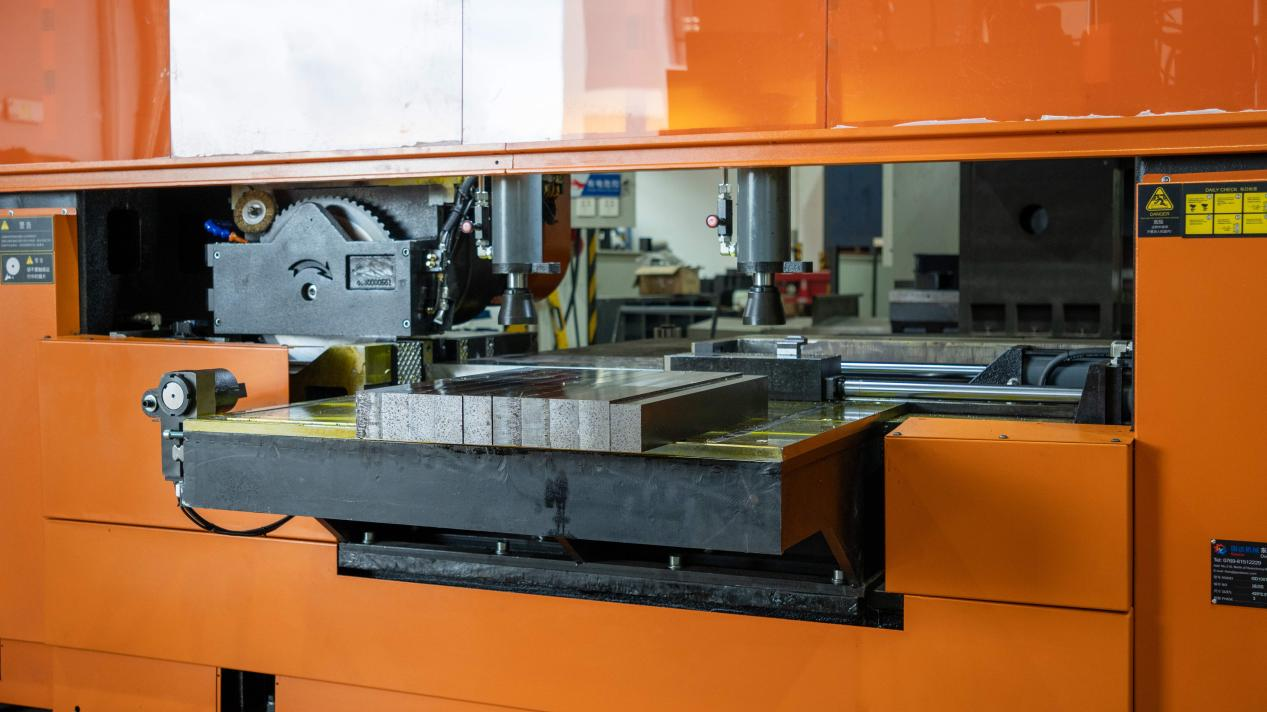
Guide alignment and guide play are also two different faults.
Bad alignment means the guide points in the wrong direction even with no load.
Guide play means it measures correctly while stopped, then shifts sideways when cutting force is applied.
That is where linear bearings, guide rollers, adjustment gibs, bushings, and carriage hardware come into the picture.
On chop-style or pivoting saws, the entire saw head can move too. A worn pivot or loose locking mechanism can change the blade plane under load even when the blade itself is perfectly straight.
For handheld metal-cutting saws, add a few more checks: the shoe, bevel lock, guide contact, and how much side pressure the operator is putting on the saw.
Blade Choice Matters
A blade is not suitable just because it fits the arbor.
Blade choice depends on the steel, hardness, section shape, section size, machine speed, feed, and the cut quality you need.
Tooth pitch matters just as much.
The space between teeth has to carry chips out of the cut. In a thick solid section, if those spaces fill before the chips can leave, cutting force rises quickly. Heat goes up, tooth damage becomes more likely, and the blade can start wandering.
Go too coarse on a thin section and the opposite problem appears: too few teeth are cutting at once, so each tooth sees a heavier impact.
This is why tooth count by itself is not enough. Use the blade manufacturer's section-size and material guidance.
Feed matters in both directions too.
Too much feed raises tooth load and can bend the blade or move the machine. Too little feed can make the teeth rub instead of cutting properly, which builds heat and wear.
Slower is not automatically safer or more accurate.
The same goes for lubrication. Traditional HSS cold saws often use cutting fluid. Some dry-cut systems are designed not to. Use the method intended for the actual saw and blade.
Use the Cut Surface as Evidence
The cut face often tells you more than the final angle alone.
| What You See | What to Check |
|---|---|
| Flat face, same wrong angle from top to bottom | Fence, blade angle, guide, spindle, or saw-head geometry |
| Cut starts square and curves sideways | Blade deflection, tooth condition, cutting load, or kerf movement |
| One cut wall is unusually polished | Blade-body rubbing or sideways load |
| Heavy marks appear only deep in the cut | Load-related deflection, chip packing, or guide/head movement |
| Damage appears mainly at the exit | Offcut movement or poor support |
| Error changes between blocks | Clamping, support, reference surfaces, or material stress |
Heat, sound, and vibration are useful clues, but I would not use any of them as proof by themselves. Blade coatings, tooth patterns, gearbox design, cutting speed, and section size can all change the way a normal cut sounds or looks.
Narrow the Cause Down
Two questions usually save the most time.
When did the problem start?
- Right after a blade change: check the blade, mounting, flanges, and runout.
- Right after resharpening: check tooth geometry and blade condition.
- After a machine impact: check the arbor, guide, carriage, fence, and saw head.
- Only with one batch of steel: look at hardness, residual stress, and surface condition.
- It slowly got worse: look at tooth wear, bearings, and guide wear.
What does the error follow?
- If a known-good blade fixes it, the original blade moves to the top of the list.
- If several good blades cut wrong in the same direction, look at the machine.
- If only certain blocks cause trouble, look at the material and workholding.
- If the error gets worse as load increases, check blade stiffness, spindle play, carriage play, and saw-head movement.
One thing I would not do is deliberately move a correct fence to cancel a bad blade. It may make one setup look better, but the machine will still be wrong when the blade changes.
Check It in This Order
- Measure the error. Is the cut tilted, curved, tapered, or only damaged at the exit?
- Check the reference face. Remove burrs and make sure the surface you are measuring from is actually usable.
- Confirm the steel. Grade, hardness, heat-treatment condition, and section size all matter.
- Clean the setup. Bed, fence, blade seating surfaces, and workpiece.
- Check clamping. Make sure the block does not move while clamps are tightened.
- Check support. Long stock and the offcut should not sag, lift, or twist.
- Inspect the blade. Look for wear, damage, uneven teeth, or pick-up.
- Measure runout. Check the blade and, where practical, the flange and arbor.
- Check machine play. Bearings, guide, carriage, head, and pivot parts.
- Check cutting data. Blade type, tooth pitch, speed, feed, and lubrication.
- Watch the kerf. If it opens or closes while cutting, the workpiece is moving.
- Change one thing. Make another cut and measure it before changing anything else.
Know When to Stop
Do not keep making test cuts if you find a cracked blade, badly damaged tooth, loose blade hardware, abnormal spindle movement, severe vibration, repeated binding, a loose workpiece, or a damaged guard.
And do not try to steer a wandering blade sideways. That adds side load to a blade that is already having trouble staying in its cutting plane.
When the Saw Is Not the Right Process
Sometimes the saw is not broken. The job is simply asking more from it than the process can reliably deliver.
That can happen when the steel is outside the approved hardness range, the section is close to the machine's practical limit, hardened areas keep damaging the blade, blade life becomes poor, or the required squareness is tighter than the saw can repeat.
At that point, a different sawing system, milling, grinding, or wire EDM may make more sense.
Also keep the next operation in mind. A mold blank that will be milled on every side does not usually need finished-part accuracy straight from the saw. What it does need is enough machining allowance left everywhere. A crooked cut that removes that allowance is the real problem.
Conclusion
A saw cut that is out of square is easier to diagnose once you stop treating every bad cut as an alignment problem. A 0.5 mm error over 100 mm is only about 0.29°, so very small mechanical movement can show up clearly on thick mold steel. Check the reference face first, then blade runout, flanges, arbor, bearings, tooth condition, clamping, support, and guide movement. Material matters too: P20+S may be around 29–34 HRC, while H13 tooling is often used around 45–50 HRC. If the kerf closes, the block may be moving. If several good blades repeat the same error, the machine probably deserves more attention than the blade.
Sources
- Swiss Steel Group — W 1.2312 / AISI P20+S Technical Datasheet. Supplied hardness approximately 29–34 HRC.
- Uddeholm — H13 / Orvar Supreme Technical Information. H13-type tooling examples around 50 HRC.
- Kinkelder — Circular Saw Blade Technical Information. HSS, TCT, and segmental circular saw blade applications.
- Scotchman Industries — Cold Saw Blade Basics and Technical Guidance. Blade sharpening, flange cleanliness, coolant, break-in, and material pick-up.
- KEYENCE / Mahr — Runout Measurement References. Radial, face, and total indicator runout terminology.
- OSHA — Machine Guarding and Circular Saw Safety Guidance. General rotating-saw and guarding principles.