

if a CNC circular saw starts a batch at the correct length and then slowly cuts shorter or longer parts, the CNC program itself is often not the real problem. Something between the commanded feed position and the finished cut is changing. The material may be slipping, the clamps may be moving, blade load may be increasing, the machine may be warming up, or the parts may simply be measured differently.
A useful first check is very simple: did the feed system move the right distance, did the material actually follow it, and did the material stay there while the blade cut? Those three questions solve a surprising number of length-drift problems.
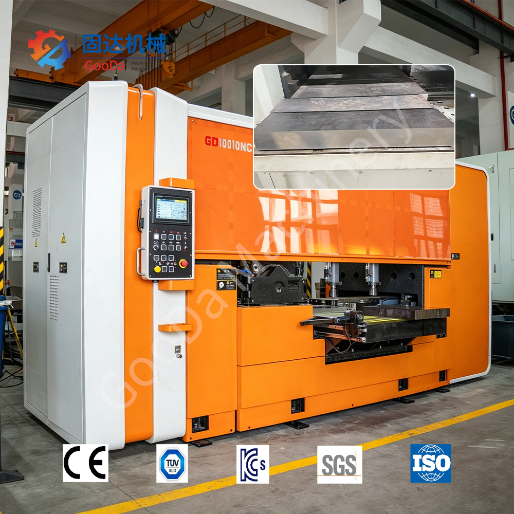
This article mainly applies to automatic metal-cutting circular saws with servo feeding, feed jaws, fixed clamps, rollers, or similar positioning systems. Different CNC machine and circular saw configurations use different feed and feedback layouts, so the exact inspection method depends on the machine.
Checks involving the blade, spindle, internal clamps, couplings, electrical components, or guarded areas should only be carried out under the machine manufacturer's service procedure. OSHA requires protection from moving machine hazards and point-of-operation hazards, and servicing work that exposes personnel to unexpected startup or stored energy requires proper energy-control procedures.[1][2]
Start with the Numbers
Do not change the length offset because one part is wrong. First measure several parts from the same batch.
| Part | Programmed Length | Actual Length | Error |
|---|---|---|---|
| 1 | 500.00 mm | 500.02 mm | +0.02 mm |
| 20 | 500.00 mm | 499.95 mm | -0.05 mm |
| 50 | 500.00 mm | 499.82 mm | -0.18 mm |
| 100 | 500.00 mm | 499.61 mm | -0.39 mm |
The first and last parts differ by 0.41 mm. That is real drift: the process is changing as production continues.
Now look at another machine cutting the same 500.00 mm length:
499.80, 499.81, 499.80, 499.82, 499.81 mm.
Those parts are all short, but the spread is only 0.02 mm. The machine repeats well. It probably has a fixed position, reference, or calibration error.
That distinction matters. A fixed offset can often be corrected once its cause is understood. Poor repeatability cannot. ISO 230-2 also treats positioning accuracy and positioning repeatability as separate machine-tool characteristics.[3]
| What You See | Where to Look First |
|---|---|
| Nearly the same error on every part | Zero, reference position, offset, calibration |
| Parts slowly become shorter or longer | Blade wear, clamping, machine warm-up |
| Random long and short parts | Chips, material seating, slipping, measurement |
| Error grows as feed length increases | Feed scale or calibration |
| Error grows after repeated feed strokes | Regripping and clamp transfer |
| Length changes after homing | Reference or home system |
| One side of the part is longer than the other | Cut squareness and blade deflection |
Check the Feed Before Blaming the Blade
A CNC display showing 500.00 mm does not prove the stock moved 500.00 mm.
The controller only knows what its feedback device tells it. On one machine that may be motor rotation. On another it may be ball-screw travel, carriage position, a linear encoder, or a measuring wheel. The material is still a separate physical object, and it can slip.
Suppose the carriage moves exactly 500.00 mm but the stock slips 0.20 mm inside the feed jaw. The control still sees the correct carriage position, while the material has moved only 499.80 mm.
That is why actual stock travel should be checked at more than one distance.
Here is an illustrative example of a proportional feed error:
| Commanded Feed | Actual Feed | Error | Error Rate |
|---|---|---|---|
| 100 mm | 99.98 mm | -0.02 mm | -0.020% |
| 300 mm | 299.94 mm | -0.06 mm | -0.020% |
| 500 mm | 499.90 mm | -0.10 mm | -0.020% |
| 1000 mm | 999.80 mm | -0.20 mm | -0.020% |
The error grows almost exactly with travel. That is the kind of pattern that should make you check feed scaling, encoder ratio, screw compensation, measuring-wheel calibration, or another distance-related setting.
A fixed error looks different:
| Commanded Feed | Actual Feed | Error |
|---|---|---|
| 100 mm | 99.82 mm | -0.18 mm |
| 300 mm | 299.81 mm | -0.19 mm |
| 500 mm | 499.80 mm | -0.20 mm |
| 1000 mm | 999.81 mm | -0.19 mm |
Here the feed distance changes tenfold, yet the error stays around 0.20 mm. That is much more suggestive of a fixed reference error, zero error, backlash, or a small position loss during clamp transfer.
One successful 500 mm test is therefore not enough to prove the whole feed system is correct.
Repeated Feeding Can Add Small Errors
Many automatic saws cannot make every positioning move in one stroke. Once the requested length exceeds the feeder travel, the machine has to feed, hand the material over to another clamp, return, regrip, and feed again.
For example, the PCS-800NC flat plate circular saw lists a 600 mm single feeding length and uses repeated feeding for longer travel. The PCS-350NC circular cold cut saw has a shorter 210 mm automatic feeding stroke.
Each handoff is another chance for the stock to move slightly.
| Feed Transfers | Illustrative Loss per Transfer | Possible Accumulated Loss |
|---|---|---|
| 1 | 0.05 mm | 0.05 mm |
| 2 | 0.05 mm | 0.10 mm |
| 4 | 0.05 mm | 0.20 mm |
| 6 | 0.05 mm | 0.30 mm |
The 0.05 mm value is only an example, not a normal specification. The important point is the pattern. If one-stroke parts are accurate but longer parts get worse as the number of regrips increases, the feed-transfer sequence deserves attention.
Check the feed jaws, regrip timing, material support, and whether the stock moves while one clamp releases and the other takes over.
Look for Material Slip
Stock can slip during rapid feeding, during deceleration, or later when the blade starts cutting.
The usual causes are not exotic:
- oil or coolant on the stock;
- worn jaw teeth;
- smooth gripping surfaces;
- scale or rust;
- round bar rotating in the jaw;
- poor jaw contact;
- low clamp force;
- heavy stock and aggressive acceleration;
- badly aligned support rollers.
Imagine the feed reaches 500.00 mm, then the stock slips backward 0.12 mm as the carriage stops. The final material position is 499.88 mm. A finished-length error in roughly that range no longer needs a complicated explanation—the physical movement is already large enough to account for it.
This is especially worth checking when a machine becomes less stable after someone increases feed speed or shortens the cycle.
Clamping Is About Grip, Not Just Pressure
The feed jaw positions the material. The fixed clamp near the blade has a different job: it must stop the stock from moving when cutting force arrives.
Consider this illustrative sequence:
| Stage | Material Position |
|---|---|
| Feed completed | 500.00 mm |
| Fixed clamp closed | 500.00 mm |
| Blade enters material | 499.94 mm |
| Cutting load increases | 499.88 mm |
The servo did its job. The stock moved 0.12 mm afterward.
Low hydraulic or pneumatic pressure can cause this, but a normal pressure reading does not prove the material is secure. For a simple hydraulic cylinder, theoretical force follows:
Force = Pressure × Piston Area
If pressure rises from 40 bar to 50 bar while piston area stays the same, theoretical cylinder force rises by 25%. Actual grip at the workpiece does not necessarily rise by the same amount. Jaw angle, contact area, friction, worn guides, oil, scale, and the shape of the stock all matter.
A clamp can show the expected pressure and still hold badly.
Look at the contact marks. A round bar may touch only a narrow strip of the jaw. A rectangular block may sit on one corner. A worn guide may let the moving jaw tilt. These are simple problems, but they can produce very inconsistent results.
More pressure is not always better either. Thin-wall tube, hollow sections, and soft aluminum profiles can deform under excessive force. If a 50.00 mm tube is squeezed to 49.70 mm while clamped, for example, the workpiece is changing shape by 0.30 mm. Once released, it springs back. That can disturb both positioning and measurement.
Clamp Timing Can Move the Stock
Sometimes neither clamp is actually faulty. The sequence between them is.
A simplified automatic cycle might be:
- feed clamp closes;
- stock moves;
- fixed clamp closes;
- feed clamp releases;
- blade cuts.
Now imagine the fixed clamp starts closing at 0 ms, its sensor reports "closed" at 180 ms, the feed jaw releases at 200 ms, but the fixed clamp does not reach full mechanical force until 280 ms.
That leaves a 100 ms period when the material may not be fully secure. If it moves 0.10 or 0.15 mm during that handoff, every servo position can still look correct.
Clamp timing is worth checking if the problem appeared after a valve change, sensor adjustment, PLC modification, cycle-time reduction, or clamp repair.
Blade Wear Raises Cutting Load
Blade wear can absolutely affect part length, but usually not because the blade simply "gets thinner."
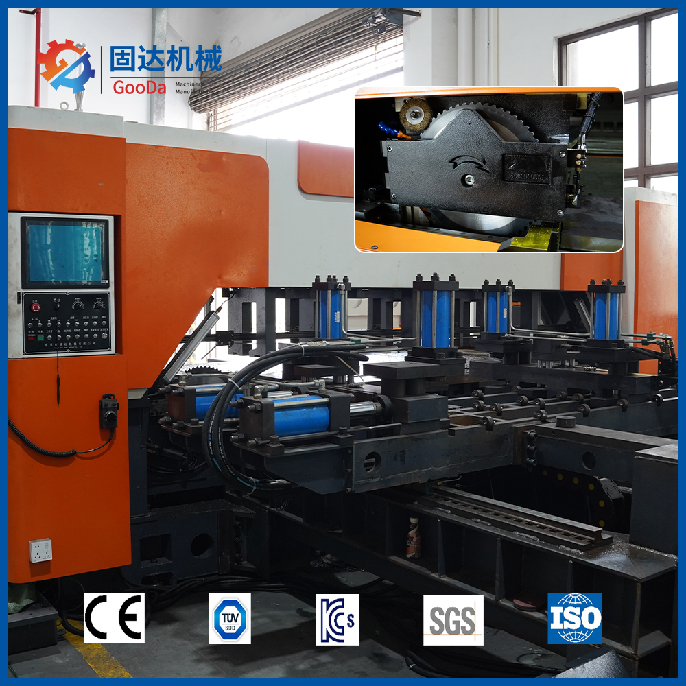
As the teeth wear, cutting force often rises. Motor load may increase, cutting time may increase, burrs can grow, and the blade can deflect more. Cutting-force monitoring is widely used to detect tool wear and damaged cutting edges.[4]
That higher load also pushes harder against the clamps.
Here is an illustrative production trend:
| Blade Cut Count | Displayed Motor Load | Length Spread |
|---|---|---|
| New | 48% | 0.06 mm |
| 1,000 | 51% | 0.07 mm |
| 2,000 | 55% | 0.09 mm |
| 3,000 | 61% | 0.15 mm |
| 4,000 | 68% | 0.26 mm |
Those values are not limits for every saw. What matters is the relationship. If your own production data shows motor load and dimensional spread climbing together as blade life increases, blade condition is part of the problem.
Still, be careful with the conclusion. If fitting a new blade restores accuracy, the blade may not be the only fault. A worn clamp can hold perfectly well with a sharp blade, then start slipping as cutting force rises.
Not Every Blade Problem Is the Same
"Worn blade" covers several different faults.
Normal tooth wear tends to develop gradually. Cutting load, cycle time, and burr size may slowly increase.
Chipped teeth often show up more suddenly through vibration, impact noise, poor chip shape, or an abrupt change in cut quality.
Built-up material on the teeth may appear only with certain alloys, lubrication conditions, or cutting settings.
Blade body distortion is different again. The teeth may still look usable, but the blade no longer holds a straight cutting plane.
The circular saw blade deflection guide goes deeper into the difference between free-running runout, blade movement under cutting load, vibration, workpiece movement, and support problems.
Kerf Is Not the Same as Length Error
This causes a lot of confusion.
Kerf is the width of material removed by the blade. Length error is how far the actual cut position is from where it should have been.
If a 3.0 mm kerf stays essentially unchanged but the stock slides 0.20 mm before the blade enters, the cut position can shift by about 0.20 mm. The error came from stock movement, not from kerf.
Kerf matters for material yield. One hundred cuts at a 2.0 mm kerf remove 200 mm of stock in total. At 1.6 mm, the same 100 cuts remove 160 mm—a 40 mm difference. That matters when planning material use, and it is discussed further in the circular saw material waste guide.
But when you are chasing batch length drift, first prove whether the stock or the cutting plane moved.
Check the Cutting Conditions
A mechanically healthy saw can still become unstable if the blade and cutting settings do not suit the workpiece.
Pay attention to blade speed, feed rate, tooth geometry, tooth count, material hardness, section thickness, lubrication, and chip removal.
Too much feed increases cutting force. Too little feed can make the teeth rub rather than cut efficiently. Poor chip evacuation can make the blade recut chips. An unsuitable tooth pitch can produce impact, vibration, or poor chip space.
If the length problem started immediately after changing material grade, blade type, or cutting parameters, check those changes before recalibrating the feed system. The steel saw blade selection guide covers the basic relationship between blade diameter, arbor, tooth count, kerf, speed, material, and section size.
Measure the Cut Face, Not Just One Edge
A part can look like it has a length problem when the real problem is an angled cut.
Take this illustrative four-point measurement:
| Measurement Point | Length |
|---|---|
| Top left | 500.02 mm |
| Top right | 500.03 mm |
| Bottom left | 500.31 mm |
| Bottom right | 500.30 mm |
The two top readings agree within 0.01 mm. So do the two bottom readings. But the bottom is about 0.28 mm longer than the top.
That is not random feed drift. The cut plane is angled.
Possible causes include blade deflection, damaged teeth, dirty flanges, spindle runout, bearing play, worn blade guides, excessive feed, stock movement, or poor support on the cutoff side.
Do not average those four values into one "500.16 mm" result. The difference between top and bottom is the useful information.
Check the Blade Mounting and Drive
If the blade already moves sideways before it touches the material, look at the mounting system first.
Qualified maintenance personnel should check flange cleanliness, burrs or chips behind the blade, blade seating, flange condition, spindle runout, bearing play, and blade guides where fitted.
If the blade runs well with no cutting load but moves after entering the steel, look harder at cutting force, blade stiffness, tooth condition, clamping, and support.
The feed drive can have similar hidden movement. Backlash may exist in a ball screw, rack and pinion, gearbox, coupling, bearing support, or carriage.
One simple clue is direction sensitivity. If the same target measures 500.02 mm when approached from one direction and 499.82 mm from the other, the repeatable 0.20 mm difference points toward lost motion or backlash rather than random blade wear.
A partly loose coupling can be even harder to catch. It may behave normally during slow movement but shift slightly during fast acceleration, reversing, or stopping. If the encoder is on the motor side of that connection, the controller may not see the mechanical loss farther downstream.
Do Not Ignore Axis Settling
The axis can eventually reach the correct position and still be slightly unsettled when the next operation begins.
For example:
- 0 ms: axis enters the controller's accepted position window;
- 20 ms: clamp command begins;
- 40 ms: cutting sequence is released;
- 90 ms: the heavy carriage and stock finally stop moving.
The final position may be fine. The cut simply started too early.
This becomes more likely after someone increases acceleration, rapid-feed speed, deceleration, or reduces dwell time. It is a timing problem, not automatically a calibration problem.
Homing Should Be Repeatable
Home or reference problems usually show themselves after a home cycle or restart.
| Condition | Programmed Length | Actual Length |
|---|---|---|
| Before homing | 500.00 mm | 499.80 mm |
| After homing | 500.00 mm | 500.02 mm |
A 0.22 mm change tied directly to the home cycle is worth investigating. Look at the home sensor, sensor mounting, encoder reference, servo zero, and physical reference position.
On the other hand, if the machine does not home at all during a 100-part batch and the length still drifts gradually, the home sensor is unlikely to be the direct cause of that particular drift.
Chips Can Use Up the Tolerance Quickly
Small chips matter when the tolerance is small.
Suppose a part is specified at 500.00 ±0.10 mm. The complete tolerance band is 0.20 mm.
A 0.15 mm chip trapped under a locating surface is already equal to 75% of that entire tolerance band:
0.15 ÷ 0.20 × 100 = 75%
Check for chips between the stock and feed jaws, fixed clamps, support surfaces, stops, and even between the finished part and measuring instrument.
Chip problems usually produce random errors rather than a smooth 100-part trend, unless chips are gradually building up in the same location.
Raw Material Can Change the Result
The saw may be unchanged while the stock is not.
Bowed bar, twisted extrusion, oval tube, diameter variation, weld seams, scale, rust, surface oil, and poor plate flatness can all change how the material sits in the clamps and on the rollers.
Hardness matters too. If a new material lot suddenly produces higher motor load and faster blade wear while the feed-position test remains unchanged, the cutting process deserves more attention than the servo calibration.
Internal stress can also fool the inspection result. A part may be cut in the right place, then bow or twist after the clamp opens.
For example:
| Condition | Edge A | Edge B |
|---|---|---|
| While supported | 500.02 mm | 500.03 mm |
| After unclamping | 500.04 mm | 500.27 mm |
If the large difference appears only after release, the stock may be changing shape. Recalibrating the feed axis will not fix that.
The First and Last Parts Can Tell You a Lot
If only the first part is wrong, inspect the original bar end and the trim-cut procedure. A rough or angled raw end is not a reliable measurement datum.
If the middle of the bar runs well but the final parts become unstable, look at the remnant. A 200 mm remnant does not behave like a 3,000 mm bar. Its support, mass, and clamping position are different.
That is why it is useful to record whether a bad part came from the beginning, middle, or end of the stock instead of treating every bad part as the same failure.
Support the Material Properly
The feeder should move the stock forward. It should not have to lift it over low rollers or drag it across badly aligned supports.
Check roller height, alignment, support spacing, stock straightness, and friction. Heavy material makes small support errors much more obvious because the clamp has less grip margin left over for acceleration and stopping.
The cutoff side matters as well. A heavy finished piece can begin dropping or rotating before the blade has fully left the cut, pulling the blade sideways. If the top of the cut looks good but the bottom develops an angle or heavy burr, check the support on the finished-part side.
Use Temperature Numbers, Not Guesswork
A cold machine and a warm machine do not behave exactly the same. Ball screws, spindle bearings, frames, hydraulic oil, and the workpiece itself all change with temperature.
A warm-up trend might look like this:
| Production Time | Actual Length | Change from Startup |
|---|---|---|
| Startup | 500.00 mm | 0.00 mm |
| 15 min | 499.90 mm | -0.10 mm |
| 30 min | 499.83 mm | -0.17 mm |
| 60 min | 499.80 mm | -0.20 mm |
| 120 min | 499.81 mm | -0.19 mm |
Most of the change happens during the first hour. The next hour changes only 0.01 mm. That looks much more like warm-up than a fault that keeps getting worse indefinitely.
You can also check whether workpiece thermal expansion is large enough to matter.
NIST's Gauge Block Handbook uses about 11.5 × 10⁻⁶/°C as an example thermal-expansion coefficient for steel gauge blocks, while noting that the exact value depends on the material.[5]
Using that value only as a rough example:
| Steel Length | Temperature Change | Approximate Length Change |
|---|---|---|
| 100 mm | 10°C | 0.012 mm |
| 500 mm | 10°C | 0.058 mm |
| 1000 mm | 10°C | 0.115 mm |
| 1500 mm | 10°C | 0.173 mm |
This is a useful reality check. If a 500 mm steel part changes by around 0.05 mm across a meaningful temperature difference, temperature could explain a large part of it. If it moves 0.80 mm with only a small temperature change, look for another cause.
ISO 1:2022 specifies 20°C as the standard reference temperature for geometrical and dimensional properties.[6]
Make Sure the Measurement Is Better Than the Problem
Before adjusting the machine, check whether the measuring process can actually detect the drift you are trying to solve.
Take a 500.00 ±0.10 mm part. The full tolerance band is 0.20 mm.
Now measure the same stable part five times:
| Measurement | Result |
|---|---|
| 1 | 500.02 mm |
| 2 | 499.95 mm |
| 3 | 500.08 mm |
| 4 | 499.96 mm |
| 5 | 500.06 mm |
The highest and lowest readings differ by 0.13 mm. That is already 65% of the entire 0.20 mm tolerance band.
Trying to diagnose a 0.05 mm machine drift with that measuring process would be difficult.
NIST defines repeatability as agreement between repeated measurements made under the same conditions.[7] A fuller Gauge R&R study can separate repeatability, reproducibility, bias, stability, and resolution.[8]
For everyday troubleshooting, at least keep the instrument, measuring point, burr-removal method, part temperature, and operator technique consistent.
A caliper displaying 0.01 mm does not automatically mean the complete measurement is accurate to ±0.01 mm.
Check Whether the Cause Is Big Enough
This is one of the quickest ways to avoid chasing the wrong problem.
| Evidence | What It Suggests |
|---|---|
| Material physically slips 0.25 mm | Enough movement to explain a similar cut-position error |
| 500 mm steel part changes by 10°C | Rough expansion estimate is around 0.058 mm using the example coefficient |
| Error roughly doubles when feed distance doubles | Feed scale or calibration deserves attention |
| All feed lengths are short by about 0.20 mm | Look for a fixed zero, reference, or transfer loss |
| Error increases after every regrip | Check clamp transfer |
| Top and bottom lengths differ by 0.30 mm | Check cut squareness before feed calibration |
A cause should not only sound possible. It should be able to explain the size and shape of the error you actually measured.
A Practical Check Order
- Measure the same part several times and make sure the measurement itself is stable.
- Measure parts from the beginning, middle, and end of the batch.
- Decide whether the problem is a fixed offset, gradual drift, or random variation.
- Test more than one feed distance.
- Compare single-feed and multi-feed parts.
- Measure actual stock travel rather than trusting only the CNC coordinate.
- Look for feed-jaw and fixed-clamp movement.
- Check the cut face for squareness.
- Compare blade cut count, motor load, burrs, and dimensional spread.
- Check backlash, couplings, and axis settling if the error follows direction or speed changes.
- Inspect chips, raw material, and support.
- Compare cold and warm production.
- Check the home system only if the error changes after homing.
- Calibrate only after repeatability is stable.
Record Enough Data to See the Pattern
You do not need complicated monitoring software. A spreadsheet is usually enough.
Useful fields include part number, programmed length, actual length, time since startup, blade cut count, motor load, cutting time, number of feed strokes, material lot, clamp pressure, and whether the part came from the start, middle, or end of the stock.
An illustrative record might look like this:
| Part | Length | Error | Blade Cuts | Motor Load |
|---|---|---|---|---|
| 1 | 500.01 mm | +0.01 mm | 200 | 49% |
| 25 | 499.97 mm | -0.03 mm | 224 | 51% |
| 50 | 499.90 mm | -0.10 mm | 249 | 56% |
| 75 | 499.78 mm | -0.22 mm | 274 | 62% |
| 100 | 499.65 mm | -0.35 mm | 299 | 67% |
The table does not prove blade wear is the root cause. It tells you that dimensional error and cutting load are changing together, so the next useful test is to see whether the stock begins moving as cutting load rises.
More Than One Fault Is Common
A worn blade and a weak clamp often appear together. The new blade cuts with less force, so the clamp holds. Later, blade load rises and the same clamp starts slipping.
Repeated feeding and worn feed jaws are another common combination. Short parts look fine because they need one feed stroke. Long parts slowly accumulate errors through several regrips.
Warm-up and manual compensation can create a problem too. If a cold machine is 0.15 mm short and the operator adds +0.15 mm, the correction may become wrong once the machine reaches its stable temperature.
And sometimes the "random length problem" is simply an angled cut plus two operators measuring different edges.
Verify the Repair Properly
If the original error needed 100 parts to appear, three good parts after repair do not prove much.
Use a similar batch length and compare the trend.
Before Repair
| Part | Actual Length | Error |
|---|---|---|
| 1 | 500.02 mm | +0.02 mm |
| 25 | 499.91 mm | -0.09 mm |
| 50 | 499.80 mm | -0.20 mm |
| 75 | 499.68 mm | -0.32 mm |
| 100 | 499.57 mm | -0.43 mm |
First-to-last change: -0.45 mm.
After Repair
| Part | Actual Length | Error |
|---|---|---|
| 1 | 500.01 mm | +0.01 mm |
| 25 | 500.00 mm | 0.00 mm |
| 50 | 499.98 mm | -0.02 mm |
| 75 | 500.02 mm | +0.02 mm |
| 100 | 499.99 mm | -0.01 mm |
First-to-last change: -0.02 mm.
That is much stronger evidence than simply getting the first part right. Where possible, keep the material, programmed length, feed method, production time, and measurement method similar to the original failed batch.
When Maintenance Should Take Over
Stop adjusting offsets and involve qualified maintenance personnel if you find loose servo couplings, excessive backlash, changing home positions, abnormal spindle or bearing noise, visible blade runout, damaged blade flanges or guides, unstable hydraulic pressure, damaged clamp parts, servo alarms, encoder faults, or sensors that require access inside guarded areas.
Operators can still collect a lot of useful information without dismantling anything: part dimensions, blade count, material lot, displayed motor load, cutting time, external pressure readings, warm-up time, burr condition, and cut quality.
Conclusion
Length drift becomes much easier to diagnose once you stop treating every bad part as a calibration problem. A feed error that grows from -0.02 mm at 100 mm to -0.20 mm at 1,000 mm points toward scale. A nearly fixed -0.20 mm error points somewhere else. A 500 mm steel part changing 10°C may move only about 0.058 mm in a rough thermal estimate, so a 0.40 or 0.50 mm batch drift needs another explanation. Measure actual stock travel, look for clamp movement, check the cut face, and make sure the measuring process itself is stable. Most importantly, run enough parts after the repair to prove the original drift is actually gone.