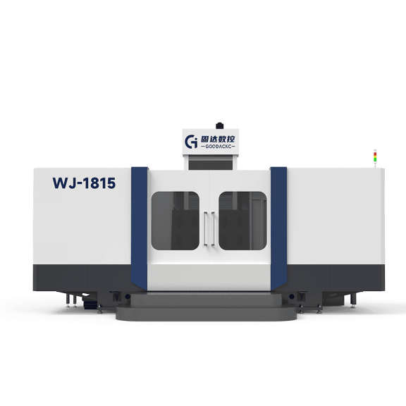
Horizontal Machining Centers
Chip Evacuation
Replace dirt with razor-sharp metal chips at 800°C, and replace a shovel with an end mill spinning at 8,000 rpm. A vertical machine cutting a 5-ton block of P20 mold steel faces exactly the same problem.
Expensive carbide inserts struggle to bite into the workpiece because they are forced to recut hot chips again and again. In the shop, this is called secondary cutting. An imported cutter head priced at RMB 1,500 can lose its edge completely in just two seconds. The shattered hard chips then scrape violently along the inner wall of the mold cavity, gouging out a groove 0.5 mm deep.
On a horizontal machine, the spindle extends parallel to the ground, and the tool cuts along the side of the mold. The moment the chips separate from the parent metal, gravity pulls them straight down. A chip conveyor below removes 50 liters of waste per minute, carrying the hot chips out of the enclosure almost immediately. Beneath the cutting zone, there is always a clear drop path.
With every rotation of the cutter, the tool meets a fresh, clean steel surface. Looking back through the maintenance records from the past three years, simply avoiding chip recutting has increased insert life by 40% to 60%.
· Chips clogging the through-coolant line and triggering spindle overload alarms
· Hardened chip buildup at the bottom of blind holes snapping M16 forming taps
· Localized piles of hot waste causing microcracks on the surface
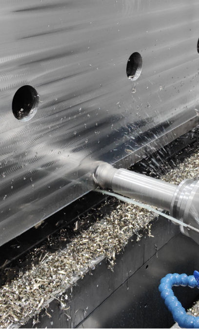
Even with gravity-assisted chip fall, chips can still hang on the wall occasionally when machining automotive bumper molds deeper than 500 mm. That is why the machine comes standard with a 70 bar through-spindle coolant system. Coolant is forced through 1.5 mm internal channels in the tool and sprays out like a pressure washer, hitting the friction zone between the cutting edge and the steel exactly where it is needed.
With an instantaneous flow rate of 30 gallons per minute, it can easily wash away sticky chips trapped in dead corners. The broken chips are blasted loose by the high-pressure coolant, slide down the inclined steel surfaces, and are finally flushed into the recovery bin at the bottom. Operators no longer need to stop the machine every 15 minutes and blow chips out of the cavity with an air gun. In the workshop, eight hours of continuous unattended cutting has become routine.
Poor chip evacuation causes more than operational inconvenience. The biggest problem is actually thermal runaway. Of the extreme heat generated when removing two tons of metal, around 80% stays attached to the chips. If hundreds of kilos of red-hot waste remain piled inside the mold, the entire base will begin to heat and expand like bread rising in an oven.
On a large machine with an X-axis travel of two meters, even a 1°C rise in ambient temperature can cause minute deformation in the internal ballscrew and lead to a positioning error of 0.01 mm. A horizontal machine lets chips leave the cutting zone in just 0.5 seconds. The heat never gets a chance to penetrate the expensive mold base. A two-ton steel block stays at room temperature from start to finish.
The shop air conditioning is set at 22°C year-round. If you scan the surface of a freshly rough-machined mold with an infrared thermometer, the reading stays steady at around 26°C. Even if you place the back of your hand on the newly cut steel surface, it does not feel hot. After the spindle has been running continuously for more than six hours, the temperature sensor on the spindle housing still reads below the safe limit of 35°C.
· Surface roughness inside hollowed areas remains below Ra 1.6
· Overall thermal deformation of massive steel blocks is held within 0.02 mm
· Tool changes on the same machine drop from three times a day to once a day
When the underlying steel does not accumulate heat, it will not warp invisibly during later operations. In the finishing stage, a very small ball nose cutter must trace dense tool marks with only 0.05 mm spacing across the steel surface. Clean chip evacuation and strict thermal control in the earlier stages are what preserve final delivery accuracy.
Vibration Resistance & Deformation Control
A 100 mm face mill loaded with six carbide inserts slams into the steel at 400 rpm. In an instant, the spindle motor delivers 1200 Nm of torque, driving the inserts 8 mm deep into the steel.
On a vertical machine, the spindle behaves like someone holding two buckets of water at arm’s length. To reach the bottom of a deep cavity, the Z-axis spindle assembly often has to hang 600 mm out in space. The rebound force generated when the cutter hits hardened steel travels up the long overhang, and the spindle above must absorb several hundred kilos of lateral force.
The farther the arm extends, the more it shakes. The tool tip can bounce against the steel surface as many as 300 times per second. The machine sounds like hundreds of drills screaming inside a steel drum, and even someone standing two meters away can feel the vibration buzzing up through the concrete floor.
That vibration gets printed onto the mold surface. What should have been a smooth side wall ends up covered with fine wave marks. A profilometer scan shows a peak-to-valley difference of 0.03 mm. The fitter then has no choice but to spend five hours bent over with an oilstone, smoothing out the file marks by hand.
A horizontal machine is built on a completely different structural concept. The base is cast into a massive T-shape. The bed alone, built purely for load-bearing, contains 25 tons of high-strength Meehanite cast iron. Inside the casting is a dense network of honeycomb ribs, with wall thicknesses exceeding 40 mm, specifically designed to absorb cutting vibration.
Instead of hanging in space, the spindle head travels tightly along the broad guideways of the column. These guideways are typically fitted with 65 mm heavy-duty roller guides, providing twice the contact area of standard ball guides. The overhang from the tool tip to the guideway face is held firmly within 150 mm.
With a much shorter overhang, cutting force has a direct path to dissipate. The several tons of thrust generated when the cutter hits mold steel are transmitted through the short spindle head into the 15-ton column in just 0.1 second. The massive cast-iron base swallows the high-frequency vibration almost completely.
Heavy cutting becomes a dull, low hum rather than a violent shriek. Two people can talk beside the machine without shouting. After machining a full 1,500 mm-long steel face, the surface feels as smooth as glass under your fingertips. A surface roughness probe glides across it and settles steadily at Ra 0.8.
The machine base also has to resist softening under the sheer weight of the mold itself. A rear mold half for an automotive dashboard, together with its iron fixture base, can weigh close to 8 tons. On a vertical machine, the worktable is mounted on a cross slide. Under an 8-ton load, the unsupported ends of the guideways can bend by 0.015 mm.
As the table moves back and forth, the shifting center of gravity causes the whole machine to twist slightly like a seesaw. A hole drilled on the left side yesterday morning and one drilled on the right side this afternoon can end up 0.04 mm out of position during assembly. Fitters can hammer through two locating pins and still fail to align the holes.
A horizontal machine clamps the 8-ton mold rigidly to a heavy rotary table. The underside of the table sits fully supported on the base, with no unsupported section anywhere. Gravity is transferred 100% vertically into the one-meter-thick concrete foundation below. No matter how the mold rotates, lateral center-of-gravity movement is kept within 50 mm.
The spindle weight is also better managed. A horizontal spindle is mounted laterally on the column, so no matter how many times it moves up and down, its weight always stays vertically loaded on the guideways and never creates a forward pitching force. At the spindle nose, a BBT50 dual-contact toolholder locks the tool flange and spindle face together rigidly, keeping runout within 2 microns.
| Measurement Item | Vertical Machine (Arm Fully Extended) | Horizontal Machine (Arm Pulled In) | Real Difference in Operation |
| Spindle overhang length | 650 mm | 140 mm | 78% shorter overhang, machine rigidity doubles |
| Surface waviness height difference | 0.035 mm | 0.008 mm | Post-polishing time drops from 5 hours to none |
| Deflection under 8-ton load | 0.018 mm | 0.002 mm | Hole misalignment over long distances reduced 9x |
| Side deflection of 100 mm cutter | 0.025 mm | 0.004 mm | The tool holds its line and hits size in one pass |
When cutting hardened H13 steel, micro-chipping on the insert edge drops by 70%. Jobs that used to require stopping halfway through a large cooling channel to replace inserts can now be completed with a single set of inserts over three identical deep cavities in a row.
Low vibration protects more than just the inserts. It also protects the machine’s extremely expensive precision ballscrews. Over years of constant vibration, the steel balls inside the ballscrew nut develop pitting from repeated impact. In less than three years, the positioning accuracy of a new machine can degrade from 0.005 mm to 0.02 mm, making it useless for precision mold work.
The vibration-damping structure of a horizontal bed acts like a thick shock-absorbing cushion for the entire transmission system. Even under full load every day, a laser interferometer test five years later still shows full-travel error rebound held within 8 microns. Once the steel block is on the table, there is no worry about whether the machine can cut it or whether the cut will wander. If the CNC program says take a 10 mm cut, the cutter removes exactly 10 mm, and the finished size comes out dead on.

Reduced Handling
A standard P20 steel block for an automotive bumper mold, together with its clamping fixture, often weighs more than 5 tons. On a vertical machine, the tool in the spindle can only approach from above, forcing the machine to attack the top of that massive steel block from straight overhead.
But molds do not just need the top face machined. The smooth side walls are full of cooling channels and ejector pin holes that also need processing. To drill the side faces on a vertical machine, the operator has to hit stop, loosen the large M24 bolts on the clamping plates with a wrench, and call the overhead crane to lift the 5-ton block off the table.
Several heavy-duty nylon slings rated for 10 tons creak under the load while two experienced fitters, sweating profusely, coordinate with one-meter pry bars. Together they cautiously rotate the steel block 90 degrees in midair and set it back down on the cast-iron table. Just waiting in line for the aging overhead crane and then slowly flipping the block can burn through two or three hours of a day shift.
And once the block is safely back on the table, the real pain begins. Re-establishing the work coordinate system is exhausting. A fitter presses a dial indicator accurate to 0.01 mm against the steel surface and taps the workpiece little by little with a copper hammer for adjustment. His eyes stay locked on the gauge, terrified that a hidden piece of debris under the base has not been fully cleaned away.
Even a tiny steel wire only 0.02 mm thick trapped between the worktable and the block can amplify into a 0.08 mm dimensional deviation at the top surface because of the workpiece height.
To machine all four side walls, the heavy block has to be lifted and flipped three times. Every time it is realigned, invisible error from the previous setup stacks on top of the next one. A reference hole drilled on day one can end up 0.15 mm off-center relative to the opposite side by day four.
In the middle of a horizontal machine’s base sits a heavy rotary table designed to turn a full 360 degrees. The operator uses the crane once to place the 5-ton rough block on the table, tightens four hydraulic clamps at the corners, and from that point on the hardest manual handling job in the shop is over. Every change of orientation is handled by the servo motor under the table.
Once the front face is finished, the CNC program issues a command, and the huge gearset beneath the table locks into motion instantly. In just 4 seconds, the massive steel block turns a full 90 degrees and stops smoothly, presenting a fresh side wall squarely to the spindle. The sequence is seamless. The tool does not even need to return to the tool magazine before continuing the cut.
All the dead time that once required human effort is turned directly into productive cutting time:
· The daily 40 minutes wasted waiting for the 20-ton overhead crane disappears
· Repetitive loosening and retightening of M24 high-strength bolts disappears
· The one hour of machine stoppage spent nudging alignment with a dial indicator and copper hammer disappears
· The high-risk possibility of a nylon sling slipping and damaging the machine or injuring workers is eliminated
Automotive mold drawings often include cooling channels at odd angles, such as a passage drilled at 15 degrees through a thick steel section. A vertical machine has no elegant answer for angled holes. The operator must rummage through the toolroom for wedge blocks of different sizes, prop the mold base up by hand, and calculate trigonometry on scrap paper with a height gauge. If the setup is off by just 0.5 degrees, a hole several hundred millimeters deep is ruined on the spot.
Inside the rotary table of a horizontal machine is a high-precision encoder capable of indexing to an astonishing 0.001 degree. If the drawing calls for 15 degrees, the control rotates the table to exactly 15.000 degrees and stops dead. An internal hydraulic disc brake clamps it instantly with up to 4000 Nm of locking torque, so even several tons of cutting force cannot shift the table by a hair.
No matter how unusual the hole angle is on the drawing, once the table rotates into place, the tool can always drill vertically into the steel as though working on a flat surface. Breakage of long, slender drills drops dramatically.
At five in the afternoon, just before the operators leave for the day, they can load the adjacent tool magazine with 120 fresh backup milling cutters and drills. Press the green start button, and the machine will keep working around the steel block for 14 straight hours, finishing roughing, semi-finishing, and drilling on all four sides in one uninterrupted cycle.
Duplex Milling Machines
Extreme Parallelism
The overhead crane places a block of P20 mold steel measuring 1500 × 1000 mm with a thickness of 800 mm onto the worktable. By the numbers, it weighs a full 9.4 tons. On an old single-head milling machine, an experienced operator can spend a full two hours just leveling and aligning it with a dial indicator.
The spindle speeds up to 800 rpm, and once the first face is milled flat, the real trouble starts. The heavy lifting slings have to be passed back under the steel block, which is then suspended in the air and flipped 180 degrees. After one layer of metal is removed, the center of gravity of that 9-ton block has already shifted by several dozen millimeters.
When it is set back down, the underside is no longer sitting in its original condition. The support blocks all have to be rearranged. If the load distribution is even slightly uneven, the moment the 15 MPa hydraulic clamps lock down, invisible distortion has already occurred inside the metal.
In the factory, veterans call this repeated flipping a second setup. The moment the workpiece is moved, some error is guaranteed. Slide a micrometer across the freshly milled surface, and the pointer jumps: over every meter of length, flatness mysteriously worsens by 0.03 to 0.05 mm.
· The moment the crane slackens off, the underside of the block can rebound by several microns
· Dust trapped between the shims and the table can easily tilt the workpiece
· Realignment and releveling wastes another 45 to 60 minutes of productive time
· Even a slight viewing angle error while reading the dial indicator can throw off the setup
On a duplex milling machine, two spindle heads stand at either end of the machine, each carrying a massive 250 mm cutter head, gripping the giant steel block like two enormous hands from both sides.
The two cutters bite into the metal simultaneously, each feeding at a depth of 5 to 8 mm. The huge cutting forces generated from both sides collide within the steel block and cancel each other out. The unilateral loading condition that normally makes the machine vibrate disappears at once.
As the cutter edges tear aggressively into the metal, the local temperature shoots past 80°C. In the past, with one-sided cutting, all the heat built up on one side, and a nearly 10-ton steel block would quietly bow toward the hot face.
With both sides cutting at the same time, heat is distributed evenly left to right across the block. Both sides expand under the same temperature and cool down together with the ambient air, holding thermal deformation firmly within 0.01 mm.
· Opposing cutting forces reduce spindle vibration to less than 1.5 microns
· Both sides heat evenly, eliminating the typical bending caused by one-sided thermal load
· Internal residual stress is released smoothly under 500 kg of cutting force
· The dual cutters advance steadily at 150 mm per minute
From large blocks down to fine details, absolute parallelism between the two faces is the lifeline of the next process. The mold base has to be drilled with dense networks of cooling channels. A gun drill with a slender drill tube may need to cut 1,200 mm deep through cast steel.
If the two reference faces are off by even 0.02 mm from the beginning, the gun drill will drift along the invisible slope. By the time it reaches the far side of the block, the error may have amplified to more than 0.15 mm.
A drifting cooling hole can cause a catastrophic failure. In many cases, only 8 mm of steel separates adjacent channels. If the high-speed drill breaks through by mistake, an entire P20 mold block worth hundreds of thousands of RMB can be scrapped instantly.
The situation becomes even more critical when multiple large steel plates are stacked together. A large automotive bumper injection mold often uses 5 to 7 solid steel plates, each 200 to 300 mm thick, stacked like a giant mille-feuille.
· The chance of gun drill deviation during deep cooling-hole drilling drops by 60%
· When several large plates are stacked, the visible light gap between them stays below 0.01 mm
· Friction loss during sliding along the guide pillars is reduced by about 30%
· Hand scraping and corrective fitting time falls from two full days to three hours
At assembly, workers use large hydraulic torque wrenches to tighten hundreds of M30 high-strength bolts. If even one plate is off by 0.05 mm in flatness, the enormous clamping force from all those bolts will distort the rest along with it.
This subtle distortion can lock up the four heavy guide pillars running through the mold. When the injection press closes with 3,000 tons of force, the mold emits a dull creaking sound, and the molded plastic parts come out with sharp burrs along the edges.
Each spindle motor delivers 50 kW of power, and the hot chips raining off the cutters crash into the conveyor below like a storm. Once the steel block is clamped in a single setup, the machine completes the entire programmed cutting sequence without interruption.
When the two massive cutter heads retract, the heavy hydraulic clamps release slowly. The P20 block on the table is left with an error between its left and right faces held within 0.015 mm, ready to move directly to deep-hole drilling.
Doubled Efficiency
A rectangular plastic mold base typically comes back from the steel yard with 15 to 20 mm of rough stock allowance still on the outside. To reduce a 1200 × 800 mm steel block to drawing size, machining just one face can leave nearly 115 kg of chips on the floor.
On an old single-head horizontal mill, the entire job depends on one spindle soldiering through alone. Its gearbox, packed with gears, drives a 200 mm cutter head, and even at full output it can remove only about 450 cubic centimeters of metal per minute.
An operator may stand there for three hours watching coolant spray hiss into white vapor, while the progress bar barely creeps forward and Face A is only a little over halfway done.
At last the first side is finished, but when he looks up, the 50-ton overhead crane is busy serving another station. All he can do is stop the machine and sit on a stool waiting for more than 40 minutes.
When the crane finally arrives, the workpiece has to be rigged, lifted, flipped 180 degrees, set down, and then painstakingly realigned with a dial indicator. By the time that entire routine is over, another full hour is gone.
On an eight-hour day shift, once you subtract waiting for the crane and flipping the workpiece back and forth, the actual time the cutter is in the metal often comes to less than four and a half hours.
A duplex milling machine tears up that old hour-by-hour way of working. Inside the large housings on both sides are two 50 kW motors, each driving a 315 mm heavy-duty cutter head.
Press the green button, and the two cutter heads bite into the block from both sides at 250 mm per minute. Each pass goes in a full 8 mm deep, shaving the hard cast steel into flying sheets of metal.
Below the table sits a 600 mm-wide chain-type chip conveyor. In less than ten minutes after startup, it is already piled with mounds of hot purple chips.
The amount of chips on the floor tells the real story best. One cutter running flat out might remove just 25 kg of metal per hour. With two cutters working at once, the machine can strip away nearly 68 kg of material per hour.
A large mold base blank that used to consume most of a day shift can now be set on the table, clamped once, and fully processed in no more than 2.5 hours from start to finish.
At year-end output review, the numbers are startling. A rough machining plant that processes 300 tons of mold steel every month can replace the output of six old single-head mills with just two duplex milling machines.
Even insert consumption moves in the opposite direction from what most people would expect. With one-sided cutting, all the load concentrates on one side, and a box of ten carbide inserts may last no more than four large mold plates.
Now, with both sides cutting simultaneously, the opposing cutting force suppresses machine vibration so effectively that under identical cutting parameters, one set of inserts can rough out seven 5-ton P20 steel blocks before the coating on the cutting edge even begins to fade.
The 45 minutes saved every day on tool changes is enough for the workshop supervisor to schedule one more 1.5-ton mold plate for roughing.
| Workshop Productivity Metric | Old Single-Head Horizontal Mill | New Heavy-Duty Duplex Mill | Difference |
| Time to remove 15 mm allowance from one side | 165 min (two passes required) | 70 min (both cutters advance together) | 95 minutes saved |
| Waiting for crane, flipping, and realignment | About 85 min (at least one full cycle) | 0 min (one setup from start to finish) | 85 minutes gained |
| Insert life (by machined area) | About 12 m² per box | About 21 m² per box | 75% longer life |
| Output in one 8-hour shift (5-ton workpieces) | Barely 1.5 pieces | A steady 4 pieces | 2.6× output |
Once rough machining starts moving like a wheel of fire, it pushes the whole workshop flow forward. In the past, the three expensive five-axis machines in the finishing area often sat idle waiting for material.
Now hot, freshly machined steel blocks roll straight off the duplex mill one after another. A raw blank dragged into the factory at 3 p.m. can already be sitting at the finish-milling station with perfectly flat datum faces before the night shift handover.
The old picture of half-finished steel blocks piled in the corner of the workshop is gone. The 80-square-meter buffer zone that used to be filled with rough stock has been swept clean and repainted with yellow lines as a dedicated forklift lane.
The power meter on the wall tells a similar story. To remove the same allowance, the old single-head machine had to keep its spindle motor running for six straight hours, and even while idling for the crane it still burned through more than ten kilowatt-hours.
The dual-head machine may have intimidating power, but it never wastes motion. A giant steel block that once consumed 450 kWh to machine flat is now held to roughly 280 kWh in total power consumption.
Safety & Cost
Any time a 12-ton P20 steel block is hanging in midair, everyone in the shop instinctively steps back. Two steel wire ropes as thick as a thumb, each 30 mm in diameter, are pulled taut and bite hard into the edges of the block.
Because an old single-head horizontal mill works so slowly, that one steel block may need to be flipped in the air three or four times a day. With more than ten tons hanging overhead, even a five-degree tilt can send it crashing down hard enough to smash a deep crater into the machine table.
Even crane operators with more than ten years of experience end up sweating through their shirts every time they work the remote. A single-head machine always needs two people nearby: one in front of the screen watching the data, the other gripping a heavy pry bar with both hands to help control the center of gravity.
· Steel wire ropes grinding against cast steel edges every day push monthly wear-related scrap rates up to 4%
· The overhead crane has to stop heavy loads abruptly so often that its brake pads do not last six months
· If an old hydraulic clamp loosens by even 1 mm, ejected chips can fly at bullet-like speed
· Workers climbing over slippery steel surfaces covered in coolant often suffer slip-and-fall injuries
Once duplex mills enter the shop, they take over the most dangerous and physically exhausting crane work. The steel block rolls into the machining chamber on the line rollers, the pneumatic clamps snap shut, and the workpiece does not need to be lifted again until the machining is completely finished.
Last year, a mold factory in the Yangtze River Delta handling large orders ran the numbers and found that simply reducing frequent heavy-lifting operations cut mandatory annual inspections and rope replacements enough to save nearly RMB 40,000 per year.
Without repeated flipping in midair, one of the plastic stools beside the machine is no longer needed. In the past, one horizontal mill running two shifts required four skilled workers. At today’s wage level of RMB 8,500 per month, labor cost alone came to more than RMB 30,000 a month.
The new dual-head machine runs almost entirely on programmed automation. One operator with a cup of tea can comfortably oversee two machines. At year-end, the workshop manager’s calculations show a reduction of RMB 25,000 per month in wages alone.
On top of that, social insurance, housing fund contributions, and summer heat allowances also decline. Even mandatory high-risk injury insurance premiums fall by 15% because the workshop is doing less heavy lifting.
· Staffing at each machine drops from a hard minimum of 2 people to 1
· Night-shift overtime premiums are reduced by about RMB 3,500 per month
· Consumption of cut-resistant gloves and steel-toe safety shoes is cut in half
· Paid downtime for crane operators waiting around while the machine works is eliminated completely
The laborers who used to wrestle pry bars at the single-head machine have all been reassigned to learn CNC five-axis machining next door. The workshop relies less and less on brute-force rough work, while the proportion of high-skill operators who understand software and code keeps rising.
Scrapping a blank is the kind of loss no one in a workshop even wants to mention out loud. The financial hit is brutal. A block of imported 718H mold steel measuring 2000 × 1200 × 600 mm costs at least RMB 120,000 just in raw purchase price.
With one-sided cutting and repeated flipping for re-leveling, all it takes is a slightly shaky hand during dial-indicator alignment. If a few passes take the dimension 0.5 mm undersize, that steel block worth well over RMB 100,000 becomes scrap metal sold by weight.
The scrap ledger in the production office drawer tells the story clearly. The old machine used to ruin two or three large blanks every year. After switching to the new equipment, the factory went 14 straight months without scrapping a single large blank.
The yield rate has climbed from 97% to 99.9%. On paper, it looks like less than a three-point change, but at year-end it translates into tens or even hundreds of thousands of RMB in additional net profit. Even selling the scrap cannot make up for the huge gap in the purchase price of specialty steel.
Even the cutting fluid bill does not stand up well under an accountant’s magnifying glass. The old machine ran so slowly that a 200-liter drum of imported premium cutting fluid could evaporate away in just half a month in the hot, dry shop environment.
With the new machine clamping a big steel block and cutting from both sides at once, total machining time is cut by more than half, and far less coolant mist is exposed to hot air and boiling off. The purchasing department now spends RMB 2,800 less per month on coolant alone.
· A 200-liter drum of cutting fluid now lasts 38 days instead of just 15
· Consumption of expensive spindle grease drops by 1.2 kg per month
· Large roof exhaust fans run four fewer hours a day, saving 150 kWh per machine
· Outsourced cleaning costs for oily floors and chips are reduced by RMB 800 per month
Even the scrap metal coming off the chip conveyor looks different. The thick, uniform chips produced by two large cutters working together are more valuable to scrap buyers than the fine shredded chips from old machines, bringing in an extra RMB 50 per ton.
Now the yellow paint on the workshop floor has been redone from scratch. With no heavy wire ropes and discarded shims scattered everywhere, the aisles are wide enough for two 3-ton hydraulic forklifts to pass side by side. The sharp smell of machine oil that used to hang in the air has long since disappeared.

Horizontal Boring Mills
A “Telescopic” Spindle
In the workshop, a solid alloy-steel spindle 130 mm in diameter is slowly extending out of the machine body. The air carries the pungent smell of machine oil mixed with cutting coolant. As the spindle extends forward 700 mm, the massive spindle housing behind it remains completely still. A 15-ton block of P20 mold steel sits securely on a rotary table rated for 20 tons, waiting to be drilled and milled.
On a conventional machining center, cutting a cooling hole 1.2 meters deep means the operator has no choice but to mount a very long toolholder extension. An 800 mm extension bar is fitted to a BT50 interface and run at 1,200 rpm. Centrifugal force immediately makes the tool tip whip from side to side, producing a piercing screech and leaving a hole wall with a roughness of Ra 6.3, effectively ruining the part.
A telescopic spindle changes the way the machine applies force. The spindle is a finely ground cylindrical shaft made from 38CrMoAl nitrided steel, with dense internal gearing inside. It moves the cutting point to within 50 mm of the machined surface. Even when the spindle extends nearly a full meter, head deflection in any direction is still held within 0.005 mm.
· Common spindle diameters: 110, 130, and 160 mm
· Typical extension length: 600 to 1000 mm
· Torque output: easily over 2500 Nm
· Tool interface: typically BT50 or ISO50
When machining a deep cavity in an automotive bumper mold, the operator may need to cut a curved surface 800 mm deep into a cast steel block measuring 3.5 meters long by 2.2 meters wide. If the bulky spindle housing moves in too close, it will definitely collide with the tall side walls of the mold. A slender quill can pass neatly through the narrow opening and reach all the way into the bottom corner.
The toolholder grips a heavy-duty 160 mm face mill, the spindle is set to 800 rpm, and feed is pushed to 1,200 mm per minute. Dark gray chips pour down like a waterfall. The stout quill absorbs tons of impact force, low vibration ripples through the shop floor, and the inserts still stay steadily engaged in the hard steel.
To survive that kind of friction, the quill surface is repeatedly heat-treated and quenched until it reaches a hardness above HRC55. Inside the spindle box are hydrostatic bearings that maintain an oil film just 0.01 to 0.02 mm thick. That thin film not only lubricates the moving parts but also absorbs the fine vibration above 100 Hz generated during roughing.
· Oil temperature control: held strictly between 20°C and 25°C
· Roundness error: must remain below 0.002 mm
· Filtration level: even 10-micron debris is removed
· Thermal compensation: the control recalculates body deformation every second
Drilling a hole is only brute-force work. The real proof of the machine comes with high-precision guide pillar bores. On a large injection mold plate, two through-holes spaced 1.5 meters apart may be required to align within 0.02 mm from one side to the other. The operator bores from one side first, retracts the tool, rotates the table a precise 180 degrees, and extends the spindle again to meet the bore from the opposite side.
A glass scale measures every micron of spindle travel and reports it to the control with 0.001 mm resolution. When you run your finger over the meeting point inside the bore, you cannot feel the slightest seam. A well-maintained machine in the hands of an experienced operator can keep running for 48 hours straight and still hold astonishing precision.
Load Capacity & Rigidity
Four steel wire ropes, each 50 mm thick, are pulled tight as they slowly lower a 35-ton steel block onto the machine table. This massive P20 mold steel block is more than two meters long, wide, and high, like an iron house.
The moment it touches the table, the floor gives off only a dull thud. The T-slot table, measuring 3000 × 2500 mm, receives it without drama. To the naked eye, the table does not seem to sink even the slightest bit.
A normal factory floor with only 20 cm of concrete has no business supporting a machine like this. The construction crew would have already excavated a foundation pit 3.5 meters deep. Just filling the base takes 120 cubic meters of C50 high-grade concrete.
The machine itself weighs 60 tons, so the foundation must be built to the extreme. Using hydraulic torque wrenches, the installers tighten dozens of M48 anchor bolts to 1500 Nm. The base locks into the concrete pit so firmly that the machine and foundation effectively become one structure.
The base supporting both the worktable and the frame is cast as a single piece of HT300 Meehanite high-strength cast iron. Before assembly, that massive casting was left outdoors for 14 months to weather naturally and relieve internal stress.
The combined dead weight of the table and workpiece, exceeding 40 tons, rests on three steel guideways each 250 mm wide. Ordinary ball-type guideways would be crushed flat under such a load. Instead, the manufacturer uses expensive hydrostatic guideways, relying on fluid pressure rather than metal-to-metal contact to bear the weight.
A pump station maintains a pressure of 6 MPa, forcing anti-wear hydraulic oil into the tiny gap between the guideways. The oil film literally lifts the table and workpiece, suspending them on a layer just 0.015 mm thick, less than one-fifth the thickness of a sheet of A4 paper.
The comparison below makes the advantage of hydrostatic support obvious:
| Guideway Type | Contact Condition | Vibration Damping Ability | Force Needed to Move 20 Tons |
| Standard ball linear guide | Steel balls in hard contact with the block | Poor; cutting vibration transfers directly | About 400 N |
| PTFE-coated sliding guide | Plastic sliding contact | Moderate; prone to stick-slip at low speed | About 1500 N |
| High-pressure hydrostatic guide | Fully separated by oil film | Excellent; oil film absorbs 80% of vibration | Only 50 N |
Now a 250 mm cutter head has been mounted on the spindle, fitted with twelve carbide-coated inserts. The 60 kW motor at the back of the machine roars to life, driving the cutter up to 450 rpm.
The operator sets the depth of cut to a staggering 15 mm and the feed to 800 mm per minute. The inserts tear into the surface of the P20 mold steel. Sparks and dark purple chips rain down against the sheet metal guards with a harsh metallic clatter.
The machine is removing nearly 2,000 cubic centimeters of metal per minute, yet the frame beside it shows not the slightest visible tremor. A cup of water in the corner shows only the faintest ripple. The enormous reactive cutting force travels through the iron structure, is absorbed by the oil film, and finally dissipates into the three-meter-deep foundation.
Machining a deep side cavity is one of the toughest tasks, because the 35-ton block has to be rotated on the table. Beneath the table, a 1.5-meter-diameter ring gear engages. A hydraulic motor delivers 4000 Nm of torque, slowly turning the mountain-like mold on top.
Once a mass like that starts moving, it is difficult to stop precisely, yet the stop position must be as exact as needlework. After rotating a full 90 degrees, a hydraulic clamping system locks the table instantly. A circular scale beneath the table reports to the control that the final indexing error is just 0.002 degree.
Not even one-tenth of a hair’s width of error is acceptable. In front of this steel giant, the boundary between roughing and precision machining disappears. In many cases, operators do not even bother to move the workpiece to another machine. They simply finish the whole job in one place.
How It Differs from an HMC
On the left side of the shop floor, a row of horizontal machining centers screams as their spindles spin up to 15,000 rpm, tearing through small aluminum parts. In the corner on the right sits an 80-ton horizontal boring mill, quietly turning a large cutter head at 400 rpm as it slowly works through a 20-ton P20 mold.
The machines on the left spend most of their energy on motion. Their X-axis feed rates can reach 60 meters per minute, crossing the table in the blink of an eye. They use lightweight HSK-A63 toolholders, which make it possible to swap a short tool in just 1.5 seconds.
By contrast, the giant on the right can barely manage 12 meters per minute at full speed. Its heavy BT50 toolholders and large geared cutter heads weigh dozens of pounds. A tool change by the automatic arm takes nearly 20 seconds just to seat the bulky cutter head into the spindle.
The old workshop manager likes to say with a stopwatch in hand: the machines on the left may run like rabbits, but try putting a 30-ton steel block on one of them and the delicate frame will collapse before it even takes a cut.
The machines on the left have twin pallets for loading and unloading workpieces, and those pallets can exchange positions in as little as 15 seconds. But each pallet can usually handle only about 1.5 tons. Put something as large as an automotive bumper mold on it, and the ballscrews underneath begin to groan.
We already mentioned the massive table on the right, three meters long and 2.5 meters wide. The anti-wear oil film beneath it can support 40 tons of dead weight with ease. Once the crane sets the steel block in place and the high-powered clamps lock it down, the workpiece can stay there for three days and three nights without moving.
When you compare the purchase specs, the difference between these two machine families is obvious:
· Machine weight: the left side usually ranges from 15 to 20 tons; the right side easily exceeds 60 tons
· Spindle torque: the left side tops out around 300 Nm; the right side reaches 2500 Nm with ease
· Tool magazine capacity: the left side may hold 120 light, slender tools; the right side typically stores only 40 heavy-duty cutters
The biggest generational gap lies in the spindle itself. On the left, the spindle is fixed and cannot extend forward. To reach the workpiece, the entire spindle housing, often 800 mm wide, has to move in toward the part along the guideways.
When the part is just a 500 mm aluminum block, bringing the housing close creates no problem. But as soon as the workpiece becomes a deep-cavity mold over two meters across with tall walls all around it, that bulky spindle housing will collide with the protruding mold structure.
The machine on the right carries a solid boring spindle 130 mm in diameter inside its body. When it encounters a deep cavity, the spindle can extend forward 700 mm while the housing stays at a safe distance. Only the slender spindle projects into the narrow metal opening to bore deep inside the part.
Even cutting tool salespeople are reluctant to visit the heavy machining shop on the right. This machine does not need vibration-resistant extended tool bars that cost tens of thousands of RMB. A simple short, thick boring bar costing only a few dozen RMB can still produce a bore wall with Ra 1.6 finish.
Even the chips on the floor reveal the difference in temperament. The chips shooting out of the coolant lines on the left are usually silver-white aluminum flakes or thin steel chips. A 0.5 MPa coolant pump is enough to wash those few hundred grams of waste straight into the floor trench.
At the feet of the machine on the right lie thick, purple-hot steel coils torn off by the inserts, each more than 2 mm thick. Without large hooks and a motorized crawler-type chip conveyor, the nearly 100 kg of scrap generated every hour could not even be transported away.
If the production line needs 500 transmission housings delivered on time every day, the owner will absolutely buy a row of the machines on the left. They are like fast-moving light infantry with rapid, concentrated firepower, built for high-volume line production.