

A CNC machining center typically needs three-phase AC power at its specified voltage and frequency, a circuit sized for the whole machine, and a continuous protective earth connection. The wiring may require L1, L2, L3 and PE, or those conductors plus a neutral. The machine’s installation diagram determines which arrangement applies.
A shop’s 380V supply will not directly suit every machine. A three-phase 220V model needs an approved voltage-conversion arrangement, while a 400V model can accept 380V only if its specified input range allows it.
Electrical Specifications to Confirm
| Item | Required Information |
|---|---|
| Supply | Phase count, rated voltage, allowed voltage range, and 50Hz or 60Hz compatibility |
| Capacity | Rated machine input current and required kVA; separate supplies for accessories |
| Connections | Neutral requirement, PE terminal, and any transformer tap settings |
| Protection | Specified upstream breaker or fuses, isolation requirements, and applicable short-circuit rating |
Use documents matching the model, serial number, and installed options. For a heavy-duty horizontal machining center ordered with through-spindle coolant or a rotary table, confirm that the electrical figures cover those options. Have an electrical professional qualified under local requirements design and connect the supply circuit.
Single-Phase and Three-Phase Power
“1~” or “1 PH” on the nameplate means single-phase; “3~” or “3 PH” means three-phase. In a 380/220V wye system, voltage is about 380V between phases and 220V from phase to neutral. That does not provide the 220V phase-to-phase supply required by a three-phase 220V machine.
If only single-phase power is available, choose a machine designed for it or obtain approval for a specific phase converter. The converter’s continuous current rating, overload capacity, and three phase-to-phase voltages under load must suit the machine.
A standard transformer cannot change single-phase power into three-phase power. A motor VFD is not a general-purpose supply for an entire CNC machine.
Voltage and Frequency
| Supply Voltage | Difference |
|---|---|
| 380V | −5% |
| 415V | +3.75% |
| 440V | +10% |
| 480V | +20% |
±10% is not a universal voltage tolerance for machining centers. Use the whole machine’s approved input range, not the range printed on one drive or power supply.
Where voltage conversion is needed, specify the transformer’s input and output voltage, frequency, and required kVA. Its selection must account for the machine load; upstream protection must also accommodate transformer inrush.
A standard transformer cannot convert 50Hz to 60Hz. A spindle drive marked “50/60Hz” does not establish compatibility for the coolant pumps, fans, or other components.
Machine Capacity and Current
The LJ-855 vertical machining center lists a 15kW spindle motor, approximately 20kW total machine power, and a rated voltage of 380V. The separate figures show why spindle power alone cannot size the incoming circuit. Obtain the rated input current and protection requirements for the actual configuration.
For a balanced three-phase load:
S (kVA) ≈ 1.732 × line-to-line voltage (V) × line current (A) ÷ 1,000
As a calculation example, 400V and 50A give approximately 34.6kVA. This is not an energy-use figure or a complete transformer-sizing calculation.
| Line-to-Line Voltage | Approximate Current |
|---|---|
| 220V | 78.7A |
| 380V | 45.6A |
| 400V | 43.3A |
| 480V | 36.1A |
At the same 30kVA, current at 220V is about 1.82 times that at 400V. Transformer input and output wiring therefore need separate sizing.
Cables and Circuit Protection
A 50A load supplied through 80m of cable may need a larger conductor than the same load supplied through 10m. Cable material, installation method, grouping, ambient temperature, and voltage drop affect the selection.
If the panel measures 400V and the machine input measures 388V under the same operating load, the difference is 12V, or 3%. Acceptance depends on the machine’s minimum input voltage and local circuit-design requirements; 3% is only the result of this example.
Check the breaker’s current rating, trip characteristics, and interrupting rating. Where applicable, the available fault current must not exceed the machine’s short-circuit current rating (SCCR), including any conditions requiring a specified upstream protective device. U.S. OSHA rules require adequate interrupting ratings and coordination between circuit protection and component short-circuit ratings.[1]
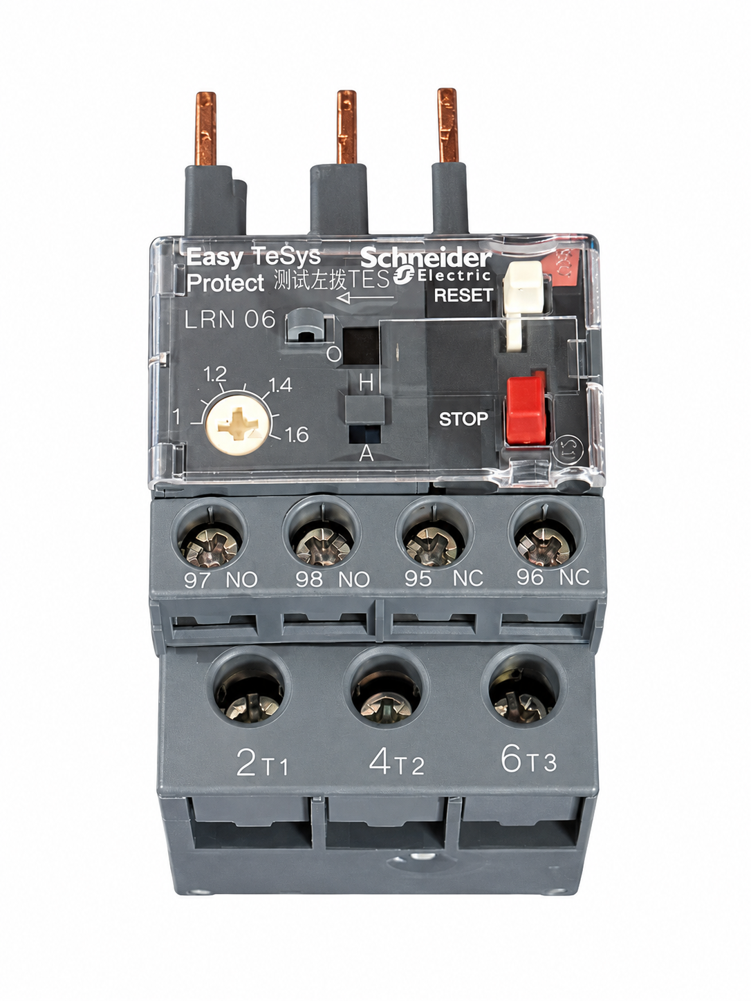
Repeated trips call for checks of the load, insulation, connections, and protection settings. Increasing the breaker rating without checking the circuit can leave the cable underprotected.
Neutral and Protective Grounding
Typical arrangements with a separate PE conductor are L1 + L2 + L3 + PE and L1 + L2 + L3 + N + PE. Four conductors at the supply point could include a neutral rather than PE, so conductor count alone is not enough.
Do not substitute neutral for PE or add an unauthorized neutral-to-earth bond at the machine. A separate ground rod or cable shield cannot replace the required protective earth connection.
OSHA requires equipment grounding paths to be permanent, continuous, and effective, and specifies how the grounding conductor accompanies the supply conductors for fixed equipment.[2]
“Below 4Ω” is not a universal CNC grounding acceptance rule. TN systems require suitable fault-loop and disconnection conditions. TT systems require coordination between earth electrode resistance and protective devices. Both require verification of the protective connections; an earth-resistance reading alone does not establish compliance.
Startup and Fault Checks
IEC 60204-1 covers machine electrical equipment from the supply connection, including protective bonding, overcurrent protection, and emergency-stop requirements.[3]
- Before power-up: Follow the installation procedure to verify supply parameters, terminal connections, and PE continuity. Isolate sensitive electronic components as instructed before insulation testing.
- During commissioning: Test emergency stops, door interlocks, and specified auxiliary motor rotation.
- For intermittent alarms: Record the code, time, machine operation, and other equipment starting on the same supply. Have a qualified professional compare these with voltage recordings during idle, spindle acceleration, and coolant startup.
A voltage dip at the time of an alarm is evidence to investigate, not proof of the cause. Mechanical binding, incorrect settings, and failed components can produce similar symptoms.