

Fixed Beam vs Moving Beam Gantry Mills: Which Fits Large Parts
Choosing a gantry machining center starts with the complete setup: the workpiece, fixtures, tooling, required features and inspection plan. The terms fixed beam and moving beam alone do not tell you whether a machine can handle that setup.
For a long or heavy component, evaluate a moving-gantry machine because it keeps the workpiece stationary during machining. For parts with large height changes, evaluate an adjustable crossbeam to position the head closer to the cut. A fixed crossbeam is worth considering when the required height range is limited. None of these arrangements guarantees better accuracy or heavier cutting by itself: compare the exact configurations and a representative test cut.
Fixed Beam, Lifting Beam and Moving Gantry: What Actually Moves?
Separate two design choices: how the crossbeam is positioned vertically and how the machine creates longitudinal travel. They describe different movements and can be combined. Manufacturer configurations illustrate this distinction: table or gantry layouts may be offered with fixed or height-adjustable crossbeams.[1]
Fixed crossbeam
The crossbeam stays at a fixed height relative to its supporting structure. The spindle head or ram provides vertical movement. On a moving-gantry machine, a crossbeam with fixed height can still travel longitudinally with the gantry. Therefore, “fixed beam” does not necessarily mean the worktable moves.
Lifting or adjustable crossbeam
The crossbeam moves vertically on the columns, often through an axis designated W. This can accommodate different workpiece heights while limiting the ram extension needed to reach a surface. Confirm whether adjustment is for positioning or controlled machining, how the beam is supported and locked where applicable, and how it is aligned after adjustment.
Moving table versus moving gantry
In a moving-table layout, the table carries the workpiece and fixtures through the longitudinal machining stroke. In a moving-gantry layout, the bridge assembly travels along the work area while the workpiece remains stationary. Some high-rail machines move a bridge on elevated guideways rather than moving a complete floor-level portal. Ask for an axis-motion drawing instead of relying on a catalog label.
Which Configuration Suits Your Large-Part Machining Job?
| Design choice | Potential benefit | What to verify |
|---|---|---|
| Fixed crossbeam | Can suit work with a consistent height envelope. | Tool reach, ram extension and clearance for the tallest complete setup. |
| Adjustable crossbeam | Can bring the head closer to surfaces at different heights. | Adjustment range, alignment, support arrangement and tool-change access. |
| Moving table | Moves the setup through a stationary portal. | Total carried load, center of gravity, permitted acceleration and the full table sweep. |
| Moving gantry | Keeps a long or heavy workpiece stationary during cutting. | Rail support, drive synchronization, service access and the complete installation envelope. |
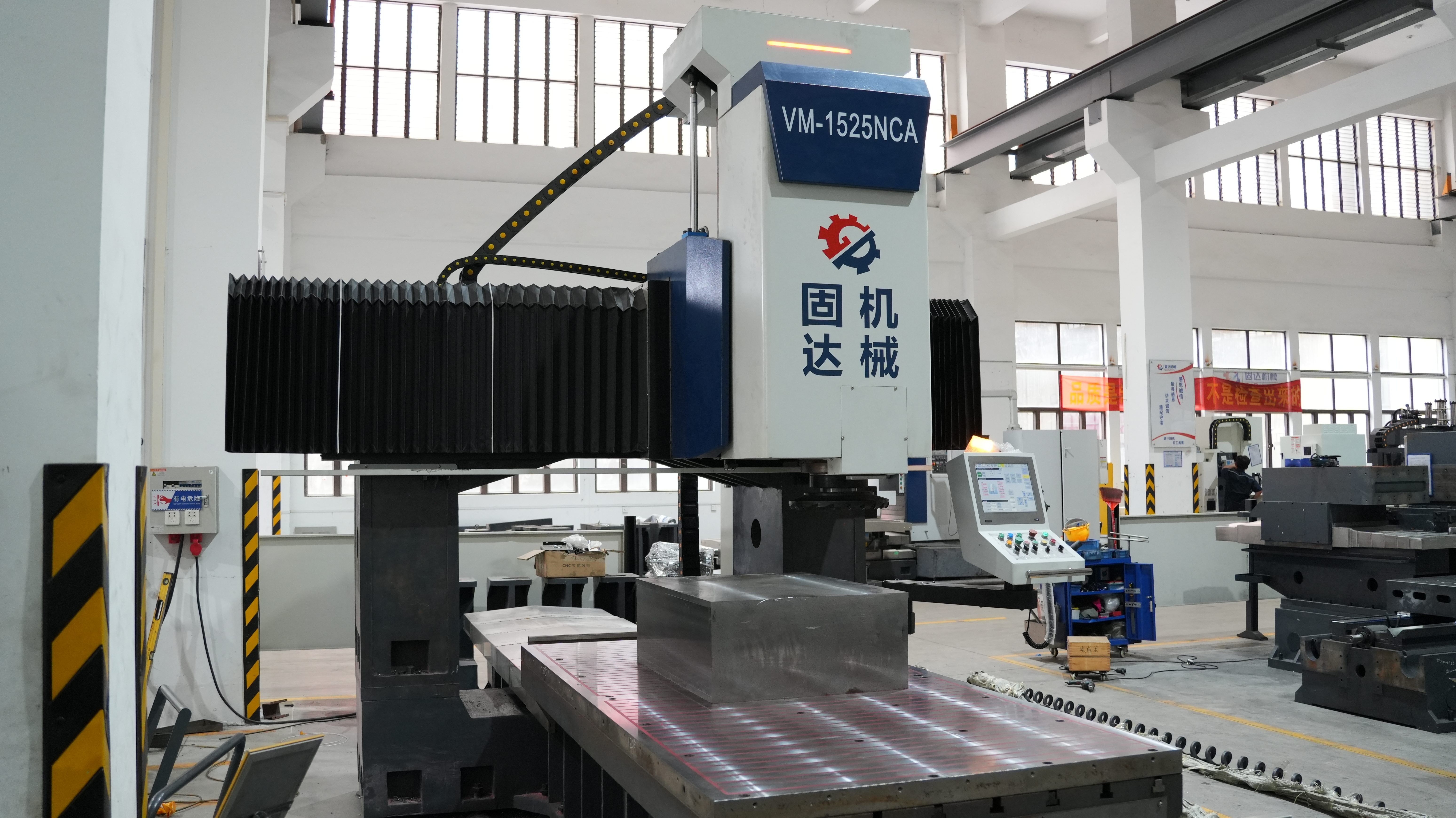
Long, heavy frames and beams: Start by checking a moving gantry, particularly when moving the loaded table would create difficult inertia or floor-space requirements. A stationary workpiece still needs suitable support and verified load distribution.
Tall housings and stepped components: Compare an adjustable crossbeam with the alternative of a longer ram or tool assembly. Check the deepest machining position, where tool reach and collision clearance may become limiting.
Precision plates and mold components: Compare both layouts against the drawing. Specify whether the requirement concerns a local bore, a face, or the relationship between features across the full part. A short-axis positioning figure does not establish finished-part accuracy over a much longer span.
There is no universal part length or weight at which one layout becomes the correct choice. The useful boundary is the capacity and demonstrated performance of the quoted machine with your setup.
Worked Selection Examples: Check the Complete Setup
The following are illustrative engineering checks, not customer project reports. They use values from the detailed specification table for the ASIATOOLS LM-3227NC double-column machining center: 12,000 kg table load and 2,500 mm clear width between columns.[2] Confirm the configuration-specific values in the signed specification before ordering.
Example 1: A workpiece below the table rating can still overload the setup
A 10,000 kg workpiece with 2,500 kg of fixtures, supports and other table-carried equipment creates a total load of 12,500 kg. That exceeds a 12,000 kg rating by 500 kg, even though the workpiece alone is below it.
Selection decision: Reduce the carried load or assess a higher-capacity configuration. A load below the rating also needs checks for its location, support area and center of gravity.
Example 2: A part that fits between the columns may leave no room for fixtures
A 2,400 mm-wide part with fixtures projecting 75 mm on each side has an overall width of 2,550 mm. If that entire envelope must pass between columns with 2,500 mm clearance, it cannot pass.
Selection decision: Revise the fixture or select a wider machine, then verify the swept volume of the actual setup. Also check cutter, holder and attachment access: column clearance and Y-axis travel are different limits.
For either example, request a layout showing the part, clamps, supports, spindle attachments and tool-change positions. A capacity number is useful only when the full machining sequence fits.
How to Verify Accuracy, Surface Finish and Heavy-Cutting Performance
A useful acceptance plan separates machine measurements from finished-part results. ISO standards provide test methods and, for some specified tests, acceptance values; they do not establish a universal performance ranking between fixed and moving beams.
1. Define what the accuracy figure measures
Request the test length, axis, direction, environmental conditions, compensation status and measurement uncertainty. ISO 230-2 addresses positioning accuracy and repeatability of individual numerically controlled axes.[3] Do not treat repeatability, positioning accuracy and workpiece tolerance as interchangeable, or scale a short-length result linearly to the entire travel.
2. Test thermal behavior over a representative cycle
Record ambient and workpiece temperatures, machine warm-up, spindle duty, axis movement and the elapsed time between cutting and inspection. Research on machine-tool thermal errors supports treating temperature control and compensation as part of the accuracy problem.[4] ISO 230-3 defines thermal-effect tests; agree on how the applicable procedures and any additional measurements will address your machine size and production cycle.[5]
3. Cut and inspect representative features
If the drawing calls for a 100 mm bore with 0.015 mm roundness or a face with Ra 1.6 µm surface roughness, put those requirements in the agreed test plan. Identify feature locations, material, tooling, fixture and inspection method. Verify both local features and any critical relationships across the part.
ISO 10791-7 covers finished test pieces for machining centers and compatible milling or boring configurations.[6] Use suitable standardized tests alongside application-specific cuts where the standard specimen does not represent your large component.
4. Compare cutting performance under the same conditions
Specify material grade and hardness, cutter diameter, insert grade, axial and radial engagement, speed, feed, tool overhang and coolant. Record cycle time, tool condition, vibration, dimensions and surface finish. A quoted cutting-force figure or depth per pass is not a complete productivity comparison.
Ask for a traceable test record: machine model and configuration, test date, setup photographs, program or cutting parameters, inspection instruments, measured results and the responsible inspector. A machining video can show the setup, while the inspection report establishes the measured outcome. Define which checks will be repeated after installation.
Floor Space, Foundations and Total Ownership Cost
Use the installation drawing to check table sweep or gantry travel, operator access, chip conveyors, tool magazines, maintenance zones and crane loading. Avoid estimating the required bay length from travel alone. Likewise, Z-axis stroke is not the same as maximum workpiece height: include fixture height, spindle-nose clearance, tool length and attachment geometry.
Base the foundation design on the supplier's loads, rail or bed support requirements, anchoring details and site conditions. A generic floor-load rating does not establish whether settlement, stiffness and vibration will be acceptable.
Compare quotations with the same required capacity, spindle and head configuration, accuracy acceptance, tooling, installation, training and service scope. Add foundation work, energy, maintenance, handling time and expected downtime.
Simple incremental payback: additional installed cost ÷ additional annual net cash benefit. Calculate the benefit from realistic production hours, contribution from additional saleable output and operating savings, after additional recurring costs. Without those inputs, a fixed price premium or payback period is not a reliable buying guide.
Frequently Asked Questions
Is a moving beam the same as a moving gantry?
Not necessarily. “Moving beam” may describe vertical crossbeam adjustment or a traveling bridge. Ask which assembly moves, in which direction, and whether the table moves during machining.
Is a fixed-beam machine always more accurate?
No. The label does not establish an accuracy class. Compare the exact machine's geometry, positioning results, thermal behavior and representative machined features under agreed conditions.
Can a moving gantry handle 20 m parts or 100-ton workpieces?
Those requirements need a configuration-specific proposal. Verify usable machining length, supported load distribution, foundation, access and full-part inspection. Specifications from a smaller gantry model do not establish capacity at that scale.
What should be included in a machine selection inquiry?
Send the drawing, maximum part dimensions and mass, material and hardness, fixture concept, critical tolerances, surface finish, required output, available floor space and crane restrictions. Identify the hardest feature to machine and inspect.
Technical Sources
- WALDRICH COBURG: portal milling configurations. See the separate table/gantry and crossbeam adjustment options.
- ASIATOOLS LM-3227 product specifications. The worked examples use the detailed table's LM-3227NC values.
- ISO 230-2:2014: positioning accuracy and repeatability of numerically controlled axes.
- Mayr et al., Thermal Issues in Machine Tools (2012), publication record hosted by NIST.
- ISO 230-3:2020: determination of thermal effects.
- ISO 10791-7:2020: accuracy of finished test pieces.