

If you are buying a horizontal face milling machine for long workpieces, start with the job, not the machine brochure.
Check seven things first: usable machining length, total loaded weight, machining faces, rotation clearance, spindle performance, workholding, and finished-part tolerance.
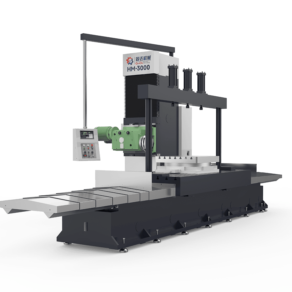
Table length alone can be misleading. The HM-3000 fixed-column model, for example, has a 3,000 × 1,200 mm worktable, but its machining capacity is 2,600 × 1,400 × 1,000 mm. The movable-column version uses a 3,200 × 1,400 mm worktable and offers 3,000 × 1,400 × 1,200 mm machining capacity.
| Check | What You Need to Confirm |
|---|---|
| Machining length | The cutter can cover the full face and clear both ends. |
| Loaded weight | The part, fixture, clamps, supports, and rotary hardware stay within the machine limit. |
| Machining faces | The machine can reach the required faces without too many extra setups. |
| Rotation | The loaded part can turn without hitting the machine or fixture. |
| Spindle | Power and torque are available at the RPM your cutter actually uses. |
| Accuracy | The acceptance test covers the real tolerance and machining length on the drawing. |
Already have the drawing? Send the raw size, complete loaded weight, material, machining faces, and stock allowance. That is enough to rule out machines that are too small before you get into optional equipment.
Check My WorkpieceSize the Machine From the Full Setup
Use the raw workpiece size and weight, not just the finished dimensions. A rough blank can be larger, heavier, and far less straight than the final part.
For a quick carbon-steel weight estimate, you can use about 7,850 kg/m³:
Weight (kg) ≈ Length (m) × Width (m) × Height (m) × 7,850
A solid 3,000 × 1,000 × 250 mm steel blank weighs about:
3 × 1 × 0.25 × 7,850 = 5,887.5 kg
That is only the steel. The machine also carries:
- the fixture plate;
- parallels and support blocks;
- clamps;
- hydraulic hardware;
- rotary or indexing equipment mounted on the table.
Also check where that weight sits. A heavy block spread across the table is not the same as the same load hanging toward one end.
Ask for the permitted static load, load distribution, center-of-gravity limits, and indexing load. If you are close to the machine limit, use the actual measured part and fixture weight instead of an estimate.
Check Machining Capacity, Not Just Table Size
The table gives you support and clamping space. It does not tell you how far the cutter can really reach.
For the HM-3000:
| Configuration | Worktable | Machining Capacity | Maximum Load |
|---|---|---|---|
| Fixed Column | 3,000 × 1,200 mm | 2,600 × 1,400 × 1,000 mm | 8,000 kg |
| Movable Column | 3,200 × 1,400 mm | 3,000 × 1,400 × 1,200 mm | 15,000 kg |
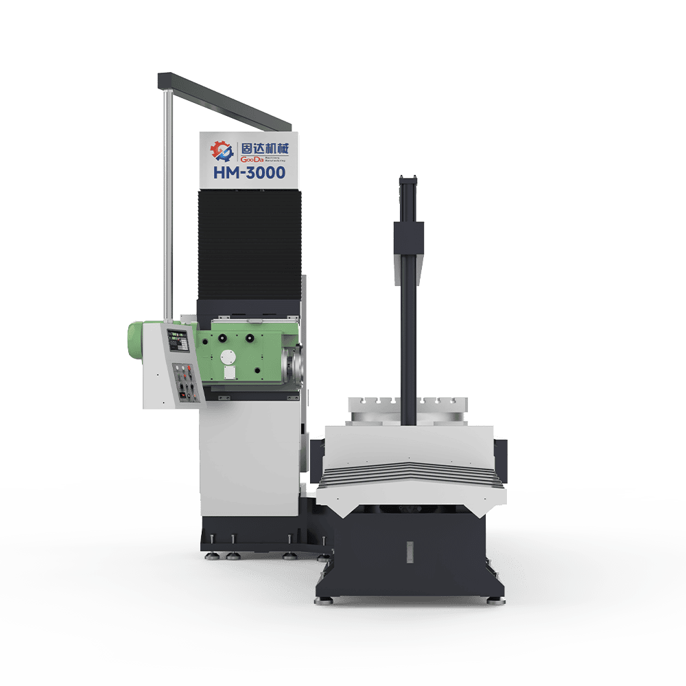
If your part is close to the machine limit, ask the supplier to put the real part into a layout drawing.
The drawing should show:
- the raw workpiece;
- fixture and clamps;
- cutter diameter;
- cutter center at the start and end of the cut;
- column and spindle position;
- axis limits.
The cutter needs room to enter and leave the surface. A 3,000 mm part does not automatically need exactly 3,000 mm of travel. Sometimes it needs more.
Check the Faces and the Turning Space
A part with two opposite faces is fairly simple. Four-side work is different.
For multi-side machining, count how many times you have to:
- unclamp the part;
- lift it with a crane;
- turn it;
- find the datum again;
- reclamp it.
On a heavy workpiece, that extra handling adds up quickly.
An indexing table can reduce those steps, but the part still needs enough room to turn.
For a rectangular part rotating around its center:
Workpiece-only swept diameter = √(Length² + Width²)
For a 2,000 × 1,200 mm workpiece:
√(2,000² + 1,200²) ≈ 2,332 mm
That number covers the workpiece only. Add clamps, fixture projections, off-center mounting, and clearance.
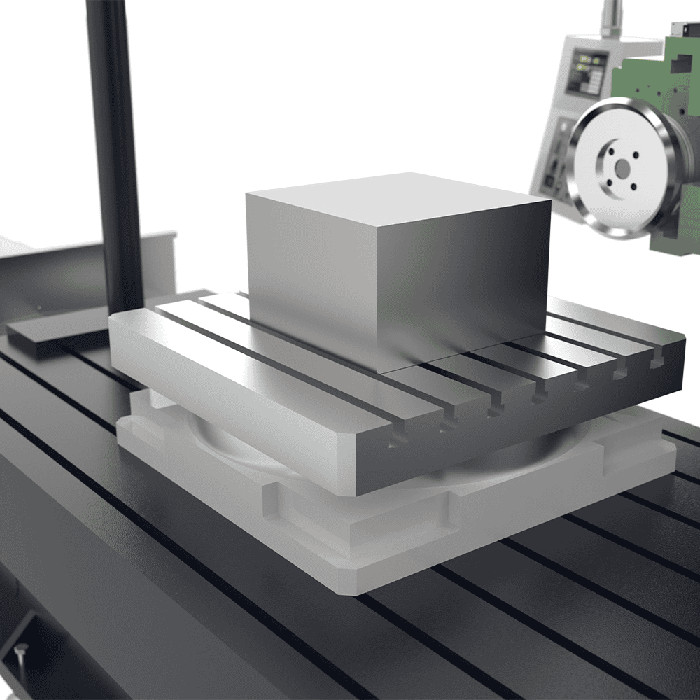
The ASIATOOLS horizontal face milling machine range includes indexing and rotary-table configurations for multi-side work. Check the full loaded turning envelope before you specify one.
Fixed Column or Movable Column?
A simple way to look at this is: do you want to move the loaded part, or move the column?
| Condition | What to Check |
|---|---|
| Long, heavy workpiece | Whether keeping the part relatively still makes support and travel easier. |
| Several support points are needed | Whether the bed or table can support them without getting in the cutter's way. |
| Shorter or lighter parts | Whether a moving-table design already covers the load and travel you need. |
| Long spindle or tool reach | Rigidity at the extension you will actually use. |
On the HM-3000, the fixed-column version offers 2,600 × 1,400 × 1,000 mm machining capacity with an 8,000 kg maximum load. The movable-column version increases that to 3,000 × 1,400 × 1,200 mm and 15,000 kg.
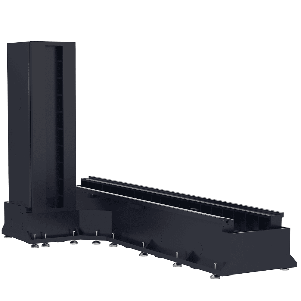
The moving-column vs moving-table guide looks at the same choice from the angle of payload movement, support, travel, and installation space.
Not sure which layout fits? Send the loaded weight, longest cut, support points, fixture height, and available floor space.
Compare ConfigurationsMatch the Spindle to the Cutter
Do not stop at spindle kW or maximum RPM.
What matters is the power and torque available where the cutter will really run.
Spindle speed can be calculated from:
RPM = (1,000 × cutting speed in m/min) ÷ (π × cutter diameter in mm)
The cutting speed has to come from the actual material, cutter, insert grade, and cutting method.
Ask for:
- continuous spindle power;
- continuous torque;
- peak torque;
- the torque/power curve;
- transmission type;
- permitted cutter diameter.
The HM-3000 fixed-column version lists an 11 kW spindle, 75–505 rpm, and a φ250 mm cutter. The movable-column version lists 11 kW, 66–662 rpm, and a φ250 mm cutter.
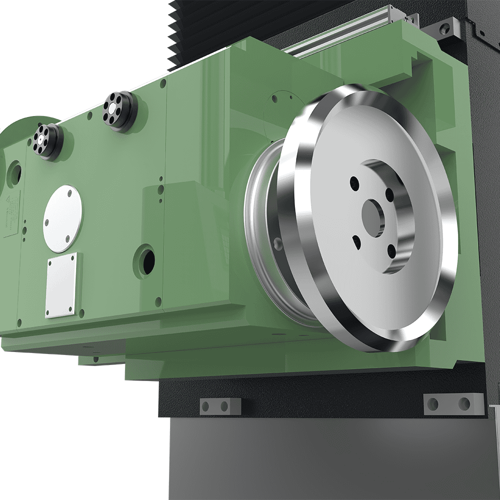
That still does not tell you whether the machine suits your cut. The supplier needs the material, cutter, stock allowance, and cutting condition.
A bigger cutter also asks more from the spindle and fixture. Do not choose one just because it fits physically.
Tell the Supplier How Much Material Comes Off
Part size tells you whether the workpiece fits. Stock allowance tells you how much cutting the machine has to do.
For a flat rectangular face:
Removal volume = Length × Width × Stock removed
For a 3,000 × 800 mm face:
- 1 mm removal = 2,400,000 mm³ = 2.4 L;
- 5 mm removal = 12,000,000 mm³ = 12 L.
The second job removes five times as much material, even though the workpiece size is exactly the same.
Give the supplier both your normal stock allowance and the worst one you actually see.
The Raw Part Matters More Than It Looks
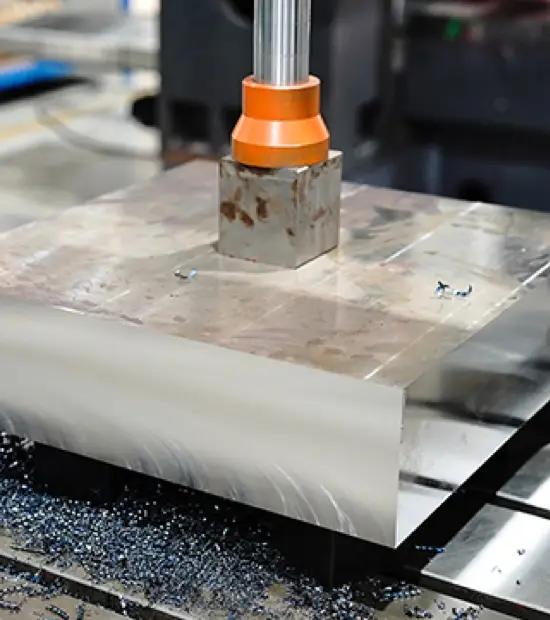
A clean pre-machined plate is one thing. A rough forging with scale and a slight bow is another.
Record:
- mill scale;
- flame-cut surfaces;
- forging skin;
- uneven stock allowance;
- bow or twist;
- hardness;
- previous heat treatment.
The large mold steel plate guide covers material grade, size, hardness, flatness, machinability, and machining allowance.
Residual stress can also move a large block while material is being removed. The stress-relief guide explains why this can show up during precision machining.
One practical trap is over-clamping a bowed part. You can pull it flat on the fixture, machine it, release the clamps, and watch some of the shape come back.
For parts with controlled flatness or parallelism, define:
- support points;
- datum surfaces;
- clamping sequence;
- clamp direction;
- roughing setup;
- finishing setup;
- whether inspection happens while clamped or after release.
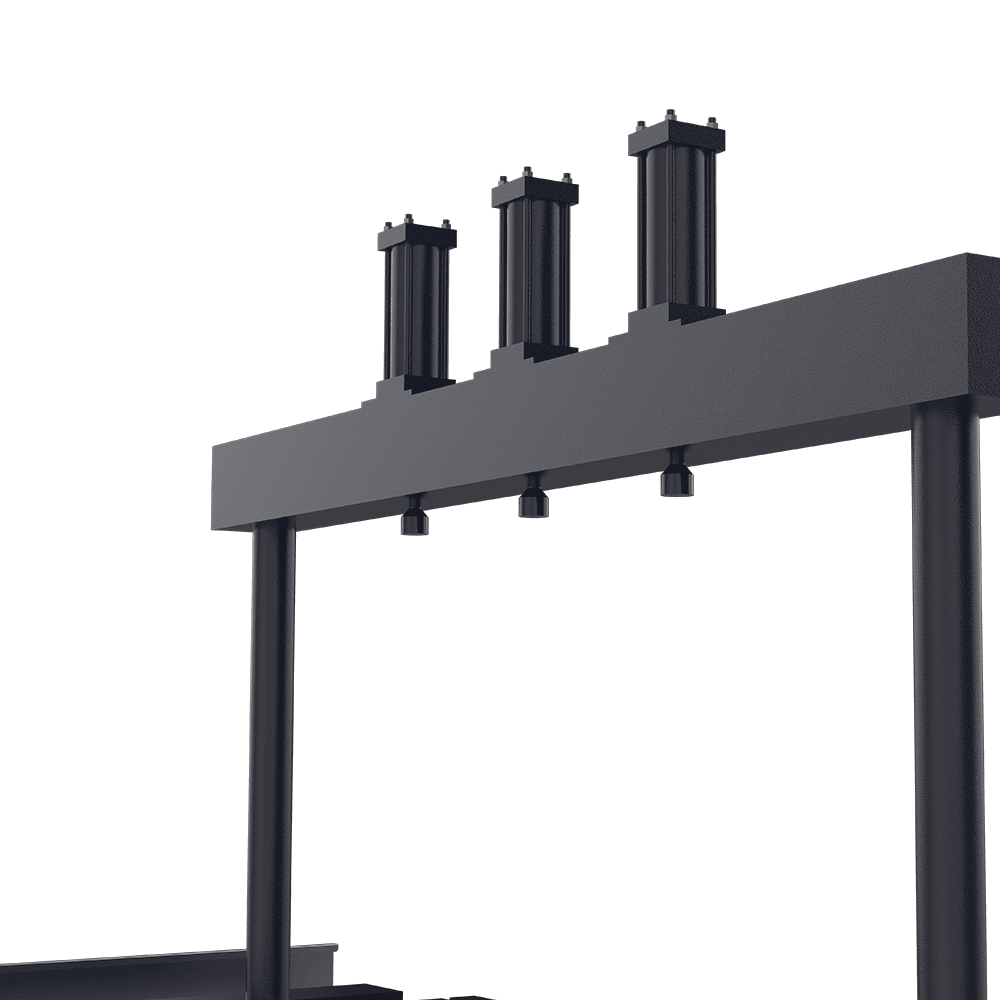
For repeated parts, a hydraulic clamping system can reduce manual clamping work. The clamping direction and force still need to suit the part.
Use the Drawing for Machine Acceptance
“High precision” is not enough. Put the real drawing limits into the acceptance plan.
| Requirement | What to Ask For |
|---|---|
| Flatness | Measurements across the full specified surface and length. |
| Parallelism | Measurement against the stated datum. |
| Squareness | Results after the planned indexing or repositioning sequence. |
| Dimension | Measured values across the required span. |
| Surface roughness | Result from the agreed material, cutter, and finishing pass. |
ISO 230-2:2014 specifies methods for determining positioning accuracy and repeatability of numerically controlled linear and rotary machine-tool axes.[1]
Axis positioning accuracy is useful machine data, but it does not prove that the finished part will meet flatness, parallelism, or squareness requirements.
ISO 230-1:2012 covers geometric accuracy testing of machine tools under no-load or quasi-static conditions.[2]
The cutting test should also look like the real job, not an easy sample near the center of the machine.
Define:
- material;
- test-piece size;
- fixture and support points;
- cutter;
- tool overhang;
- stock removal;
- roughing and finishing sequence;
- measurement positions;
- acceptance limits.
If your real cut runs near the end of an axis, test there. If production uses a long tool extension, include that too.
Use the drawing as the acceptance basis. Send the critical tolerance, longest cut, material, stock allowance, and fixture details so the trial can match the real job.
Review My DrawingLook at the Whole Cycle
Two heads do not mean twice the output.
Count the whole cycle:
- loading;
- clamping;
- datum setting;
- roughing;
- finishing;
- indexing or crane repositioning;
- inspection;
- chip clearing;
- unloading.
A rotary table earns its keep when it removes lifting, reclamping, and datum resetting. A dual-head setup only helps when both heads cut real cycle time.
Horizontal Face Milling Machine or Gantry Machine?
| Main Work | Machine to Check |
|---|---|
| Long vertical sides and end faces | Horizontal face milling machine |
| Large horizontal plate or block surfaces | CNC gantry milling machine |
| Top milling plus drilling, boring, pockets, and tool changes | Gantry machining center |
A horizontal face mill may finish four side faces and still leave the top, bottom, holes, pockets, and other features untouched.
If those operations make up most of the job, compare the complete process before buying a dedicated face-milling machine.
Do Not Forget the Chips
Heavy stock removal can fill the work area faster than people expect.
Check:
- where chips fall;
- chip-conveyor position;
- conveyor capacity;
- coolant return;
- fixture pockets that trap chips;
- access for manual cleaning.
If operators have to stop and shovel chips out of the cutting area, that time belongs in the cycle-time calculation.
Check the Space Around the Machine
The HM-3000 fixed-column version is listed at about 7,800 × 2,400 × 3,300 mm.
The movable-column version is about 7,250 × 4,230 × 3,650 mm.
That is not the full working area. Add room for:
- full axis movement;
- loaded workpiece rotation;
- open doors and guards;
- electrical cabinets;
- coolant equipment;
- chip-conveyor removal;
- maintenance access;
- raw and finished part staging;
- crane or forklift access.
Check Guarding and Heavy-Part Handling
OSHA 29 CFR 1910.212 requires machine guarding against hazards including points of operation, rotating parts, flying chips, and sparks. Milling machines are specifically listed among machines that normally require point-of-operation guarding.[3]
For U.S. workplaces using overhead or gantry cranes, OSHA 29 CFR 1910.179 covers requirements including rated loads, inspection, and load handling.[4]
OSHA 29 CFR 1910.147 covers hazardous-energy control for covered servicing and maintenance where unexpected startup, energization, or stored energy can cause injury.[5]
Use the safety rules that apply where the machine will be installed.
What to Put in the RFQ
| Item | What to Send |
|---|---|
| Raw workpiece | Maximum L × W × H |
| Loaded weight | Complete mounted setup |
| Material | Grade and hardness |
| Stock removal | Normal and maximum allowance |
| Machining | Required faces and any drilling, boring, or pocket work |
| Tolerances | Flatness, parallelism, squareness, size, and surface roughness |
| Tooling | Existing cutter or required cutter range |
| Workholding | Fixture, support points, and clamping method |
| Handling | Crane or forklift capacity and loading direction |
| Production | Batch size and expected volume |
| Installation | Available floor area, height, and foundation limits |
Ask the quotation to state:
- usable machining envelope for your part;
- maximum permitted loaded weight;
- loaded rotation envelope and indexing load where needed;
- recommended cutter and spindle operating range;
- fixture concept;
- machine layout with the actual workpiece;
- acceptance-test conditions;
- foundation and installation requirements.
Do not ask only for a “3-meter machine.” Send the raw size, loaded weight, machining faces, material, stock removal, and drawing tolerance. That gives the supplier something real to size the machine around.
Request a Machine ConfigurationFAQ
Can a 3,000 mm table machine a 3,000 mm workpiece?
Not always. Check the usable machining capacity, cutter entry and exit, fixture space, and axis limits. Table length and cutting length are not the same thing.
When should I look at a movable-column machine?
It is worth checking when a long or heavy loaded part is easier to keep relatively still. Compare machining envelope, load, rigidity, floor space, and foundation requirements with the fixed-column version.
When is a rotary or indexing table useful?
When several side faces need machining and indexing can save repeated lifting, reclamping, and datum setting. Check the full loaded turning envelope first.
Before You Order
- Fit: Can the cutter cover and clear the full required face?
- Load: Is the complete mounted setup within the permitted load?
- Rotation: Can the loaded part turn through every required position without a collision?
- Structure: Does it make more sense to move the table or the column?
- Cut: Can the spindle run the required cutter at the real cutting condition?
- Accuracy: Does the acceptance test prove the drawing requirement across the required length?
- Process: What loading, turning, drilling, boring, inspection, and chip handling still remain?
Get those answers before you place the order.