

Start with seven things: steel grade and condition, hardness, clamped workpiece size, loaded weight, chamfer geometry, drawing tolerance and required output.
Use the hardest regular job and the largest workpiece you normally clamp as your baseline. From there, compare spindle performance, cutter size, workholding, machine capacity, cycle time and the accuracy you actually get on the finished part.
Maximum RPM and motor power are easy numbers to compare, but they should not decide the purchase. The machine has to hold the required chamfer on your real production material, at a cycle time and tooling cost that make sense.
Start With the Actual Steel Condition
“Mold steel” covers a lot of ground. A pre-hardened P20 plate is not the same cutting job as a heat-treated tool-steel insert.
Write down the grade, heat-treatment condition and hardness at the point where chamfering takes place. ISO 6508-1:2023 defines Rockwell hardness testing methods for metallic materials, including the HRC scale.[1]
If you run several materials, focus on the one that creates the toughest regular cut. Hardness is part of the picture, but not the whole picture. Alloy composition, heat treatment, surface condition, interrupted cutting, cutter engagement and workpiece geometry can all change how the material cuts.
ASIATOOLS' mold and tool steel range includes P20, H13, H11, D2, 420 and 1045/C45. If you ask for a cutting test, send the actual grade, hardness range and material condition along with the drawing.
Define the Chamfer From the Drawing
Four numbers matter straight away: chamfer size, angle, tolerance and edge length.
C0.5 × 45°, C2 × 45° and a 30° bevel are not the same cutting job. A larger chamfer means more cutter engagement and more material to remove. Change the angle and you may need different cutter geometry as well.
Separate the chamfer you make every day from the largest one you might occasionally produce. There is little value in paying for maximum capacity that almost never gets used.
Also be clear about what the drawing controls. Depending on the drawing convention, inspection may be based on leg length, face width or another defined feature.
If the chamfer gets wider or narrower along the same edge, look at workpiece location, clamping, cutter runout, tool wear and machine geometry first. A CNC offset can fix a uniform size error. It will not fix the cause of a tapering chamfer. ASIATOOLS covers the usual checks in its guide to uneven chamfer width on mold steel blocks.
Check Clamped Size and Loaded Weight
Do not size the machine around the bare workpiece. Size it around the workpiece after it is actually clamped.
Leave room for:
- the workpiece
- locating stops
- clamps or magnetic workholding
- support blocks
- cutter entry and exit
- spindle clearance
A block may fit inside the published processing range and still leave no sensible space for clamps or cutter access.
The current ASIATOOLS CNC chamfering machine series lists these DJX3 capacities:
| Model | Listed Processing Range | Maximum Chamfer | Maximum Load |
|---|---|---|---|
| DJX3-1000-600S | (20–300) × (150–600) × (150–1000) mm | C4 | 2,000 kg |
| DJX3-1200-700S | (20–300) × (150–700) × (150–1200) mm | C4 | 2,000 kg |
| DJX3-1400-800S | (20–300) × (150–800) × (150–1400) mm | C4 | 2,000 kg |
Compare these sizes using the full clamped envelope. If your workpiece sits close to the listed width or length limit, draw the fixture layout before ordering rather than assuming it will fit.
Loaded weight needs the same treatment. Include the fixture, not just the steel. For a rough carbon-steel calculation, 7.85 g/cm³ is commonly used as a nominal density:
Mass = length × width × thickness × density
Use the grade-specific density when lifting or machine-load calculations need better accuracy.
Magnetic chucks, hydraulic fixtures, support blocks, rotary devices and anything else sitting on the table all add to the total. The loading method also has to suit the final weight and the machine enclosure.
Check the machine against the full workpiece setup
Send the maximum L × W × H, loaded weight, fixture layout, steel grade, hardness, chamfer size and tolerance. These can be checked against the DJX3 working range before quotation.
Check Your Workpiece Size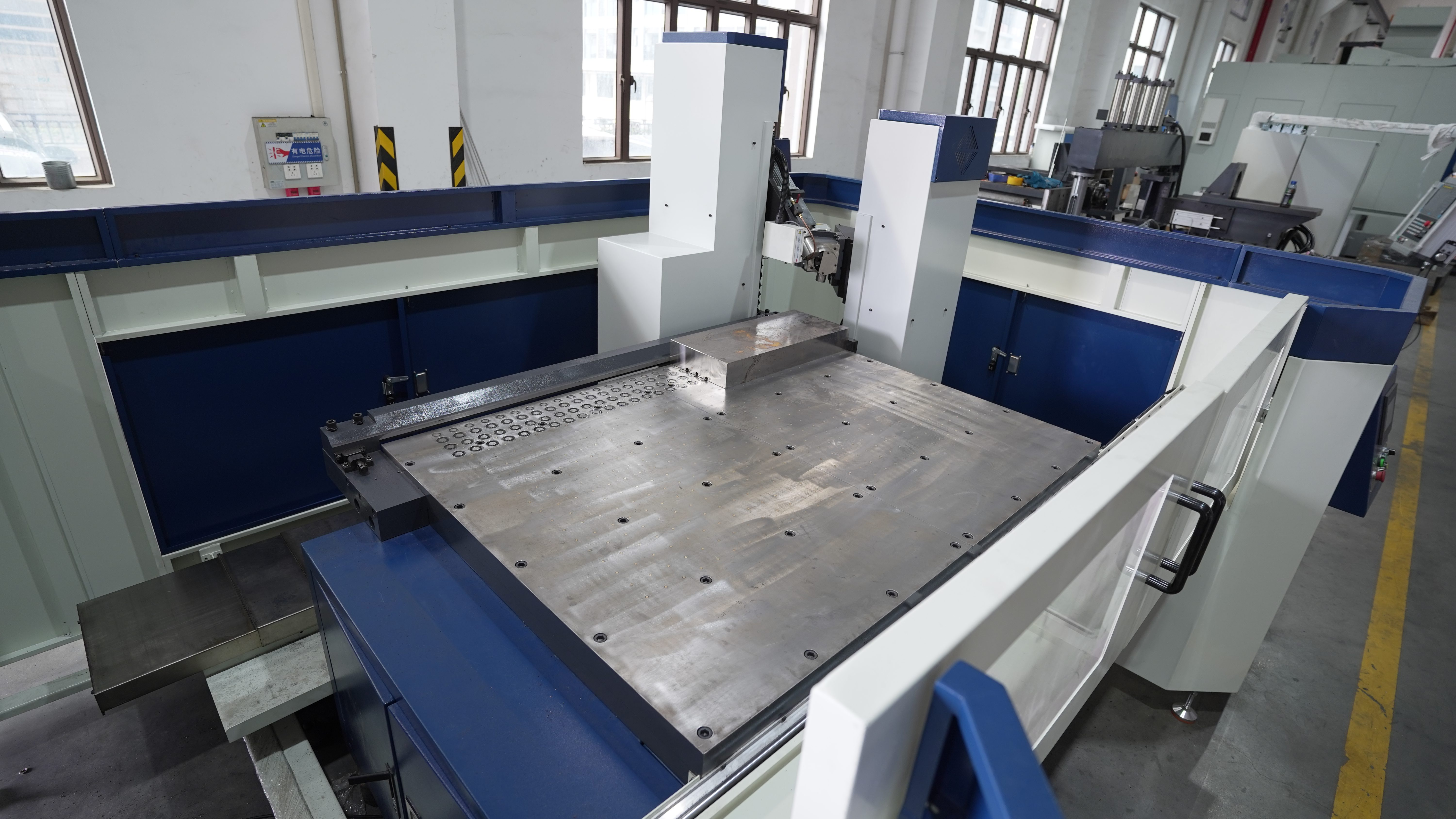
Match the Spindle, Cutter, and Steel
Maximum spindle RPM on its own tells you very little.
The RPM you actually need depends on cutter diameter and cutting speed. Feed also changes with tooth count, feed per tooth, material, cutter geometry and engagement.
Ask the supplier to spell out the complete test setup:
- cutter diameter
- insert or carbide grade
- coating
- actual spindle RPM
- feed rate
- number of passes
- steel grade and hardness
- chamfer size
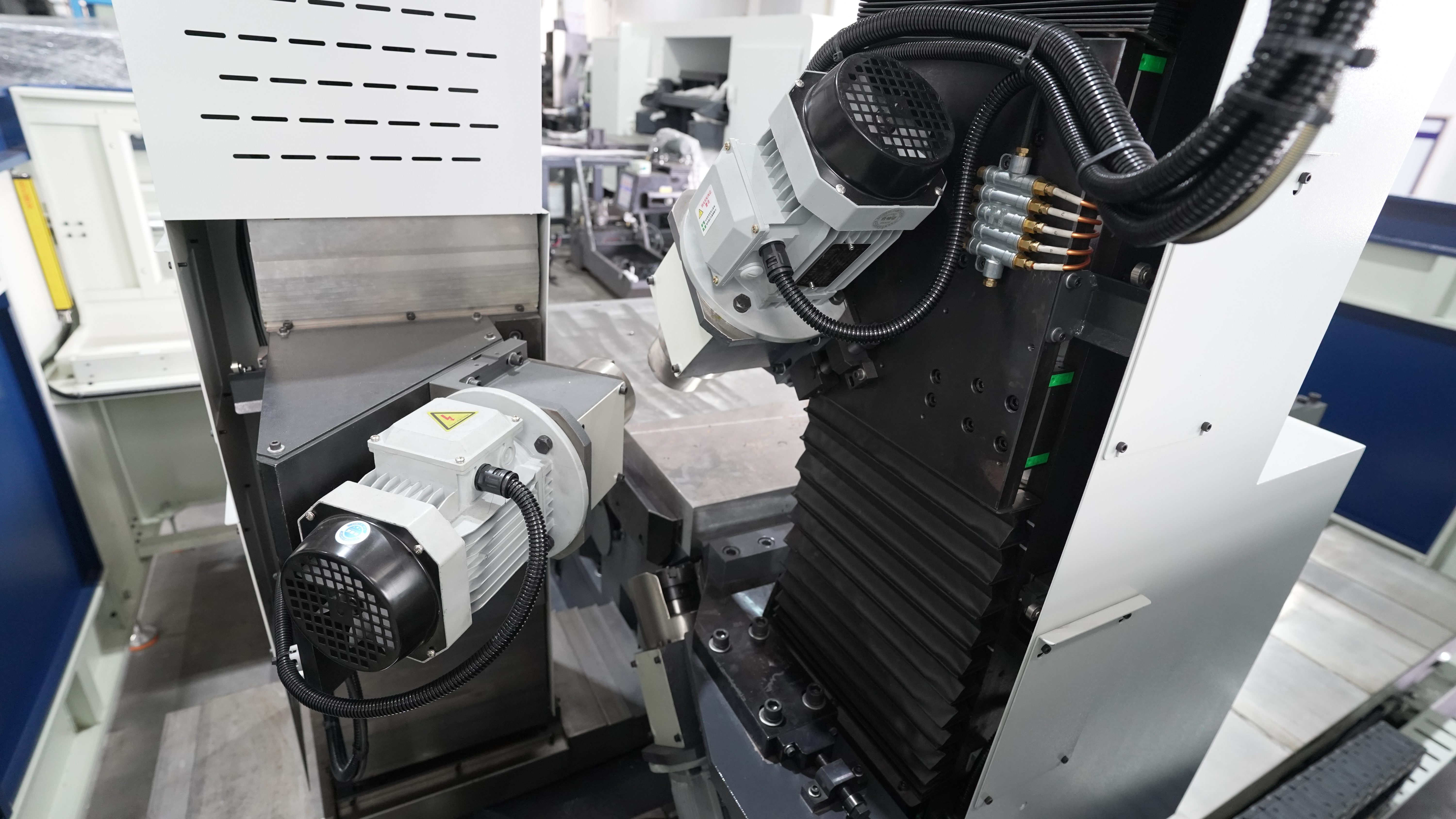
The current DJX3 series lists a φ90 mm cutter and 2,825 rpm spindle speed. Those two figures say much more about the intended chamfering process than simply comparing maximum RPM with a general-purpose machining center.
If the supplier has it, ask for the spindle torque curve. Rated motor power does not tell you how much torque is available at the speed where the cutter actually runs.
The cutter has to match the steel too. Carbide grade, coating, edge geometry and cutter diameter all affect tool life, cutting stability and surface finish.
A nice result on softer steel proves very little if your production material is harder or more difficult to cut. Test with material condition, chamfer size, tooling and parameters that are close to the real job.
Judge the Machine From the Finished Chamfer
Rigidity is not one casting or one machine-weight figure. It is the stiffness of the whole cutting loop: cutter, holder, spindle, machine structure, table, fixture and workpiece.
When that loop is not stiff enough, you may see:
- chatter
- chamfer width that changes along the edge
- poor surface finish
- unstable cutting noise
- uneven cutter wear
The risk gets higher with heavier cutter engagement, longer overhang, difficult material or weak workholding.
A heavier machine is not automatically a more rigid cutting system. The finished workpiece is the better judge.
Axis accuracy and finished-part accuracy are different things. ISO 230-2:2014 specifies methods for testing positioning accuracy and repeatability of numerically controlled machine-tool axes.[2]
The finished chamfer is also affected by cutter runout, wear, clamping, datum error, workpiece straightness, cutting force and temperature.
ISO 230-12:2022 addresses machine-tool testing through finished test pieces and covers several sources of machining error beyond basic axis positioning.[3]
If the drawing controls the chamfer, then the finished chamfer should be part of the acceptance test.
Define the Cutting Test Before Ordering
Agree on the test conditions before the machine trial. Otherwise, a good-looking sample does not tell you much.
| Item | Define Before Testing |
|---|---|
| Material | Grade, condition, and hardness range |
| Workpiece | Representative dimensions and loaded setup |
| Chamfer | Size, angle, and edge length |
| Tolerance | Finished drawing requirement |
| Tooling | Cutter, insert/grade, coating, toolholder |
| Inspection | Datum, gauge, and measurement locations |
| Cycle time | Exact start and finish points |
| Tool condition | Wear or chipping acceptance criterion |
Measure the same locations on consecutive parts. On a long edge, check several points rather than measuring only the middle. If someone changes an offset, replaces the cutter or adjusts the fixture during the test, write it down.
Run enough pieces to show the amount of variation that matters for your job. There is no magic sample count that suits every machine purchase. High-volume parts, tighter tolerances and expensive workpieces justify a longer test.
Temperature matters when tolerances get tight. ISO 230-3:2020 defines methods for evaluating thermal effects from environmental temperature, rotating spindles, moving linear axes and rotary components.[4]
Follow the manufacturer's warm-up procedure, then repeat the same measurements once the machine reaches a normal production temperature.
Check Workholding Before Adding CNC Compensation
The fixture has a simple job: establish the datum, hold against cutting force, support the block near the cut and leave enough room for the cutter and chips.
The CNC axis can return to the same programmed position every time and you can still get a different chamfer if the workpiece moves or sits on chips.
For repeat parts, fixed stops and consistent clamping help reduce setup variation. A hydraulic clamping system can reduce repeated manual clamping when the fixture and part shape suit hydraulic workholding.
Do not use chamfer compensation to cover up poor reference geometry. If the block needs flat, parallel or square faces before edge work, prepare those surfaces first. ASIATOOLS' CNC duplex milling machines are intended for opposite-face and multi-side preparation of mold and steel blocks before later machining.
Measure the Full Production Cycle
Time the whole sequence:
load → locate → clamp → measure/set → cut → rotate if required → clean → unload
Spindle-on time is only part of the job.
Also count how many edges you can finish before the block has to be turned. With a heavy mold block, avoiding one crane lift or rotation can save more time than pushing the cutting feed a little higher.
The ASIATOOLS chamfering series states that three edges can be chamfered in one cycle and all edges completed through three cycles. Check that sequence against your real workpiece and fixture before putting it into a production-time estimate.
If you are adding automation, start with the longest repeated non-cutting step. Measure loading, alignment, clamping, rotation, tool setting and cleaning separately.
For a simple production estimate:
annual time saved = time saved per part × annual part quantity
Then compare those saved machine and labor hours with the extra equipment, maintenance, floor-space and integration cost.
Check Chip, Coolant, and Safety Controls
Chips on a locating face can shift the part. Chips trapped around a finished edge can scratch it and add cleaning time.
Look at chip direction, collection capacity, fixture access, enclosure coverage and how often someone has to stop production to clean the area.
Where metalworking fluids are used, exposure can occur through aerosols, skin contact and splashing. NIOSH identifies enclosure and ventilation among the engineering controls used to reduce metalworking-fluid aerosol exposure.[5]
Safety requirements vary with machine design and destination market. ISO 16090-1:2022 specifies safety requirements for machining centres, milling machines and transfer machines within its scope.[6]
For U.S. workplaces, OSHA 29 CFR 1910.212 requires guarding against hazards including points of operation, rotating parts, flying chips and sparks.[7]
- guards and enclosure
- access doors and interlocks where applicable
- emergency-stop locations
- chip containment
- safe loading access
- visibility of the cutting area
- maintenance access
OSHA 29 CFR 1910.147 covers control of hazardous energy during covered servicing and maintenance activities in U.S. workplaces.[8]
Before purchase, confirm which standards and documents apply at the final installation site.
Compare Cost Per Good Part
The machine price is only the first number on the spreadsheet.
Include:
- full cycle time
- operator time
- cutters and inserts
- fixtures
- coolant and consumables
- routine maintenance
- tool-change downtime
- unplanned downtime
For tooling:
tool cost per good part = total tool cost ÷ acceptable parts produced
Add the machine and labor time spent indexing inserts, changing tools, presetting and correcting offsets.
After repeated production-like cutting, inspect the cutter. Normal wear, chipping, heat damage and uneven wear point to different problems, so it helps to record how the tool actually fails.
Use a realistic annual production quantity when comparing machines. An ROI calculation built on a volume you will never run is not much use.
Send Complete Data With the RFQ
| Category | Information to Provide |
|---|---|
| Material | Grade, standard, heat treatment, hardness range |
| Workpiece | Typical and maximum L × W × H |
| Loaded Weight | Workpiece plus fixture and table-mounted equipment |
| Chamfer | Normal size, maximum regular size, angle, edge length |
| Quality | Tolerance, surface requirement, inspection method |
| Production | Batch size, parts per shift, operating hours |
| Handling | Manual, crane, roller, pallet, or automated loading |
| Site | Power supply, available floor space, destination country |
| Documents | Representative drawings and acceptance requirements |
If you buy mold steel as prepared stock, match the incoming block size and condition to the downstream machine envelope. ASIATOOLS also supplies custom mold steel blocks, so stock dimensions and machining allowance can be set before the chamfering process is finalized.
Use the drawing as the machine specification
Send the drawing with material condition, hardness, loaded weight, chamfer tolerance and required output. The machine can then be matched to the workpiece and tested under relevant cutting conditions before quotation.
Submit Your DrawingUse These Selection Criteria
| Do Not Select By | Check Instead |
|---|---|
| Highest maximum RPM | Required RPM, cutter diameter, torque, feed, and actual cutting result |
| Largest motor | Spindle performance plus cutting-loop rigidity |
| Largest table | Clamped workpiece envelope and loaded weight |
| Largest maximum chamfer | Normal and maximum regular drawing requirements |
| One successful sample | Repeated parts measured at consistent locations |
| Axis accuracy alone | Finished chamfer accuracy under production-like conditions |
| Cutting time alone | Full loading-to-unloading cycle |
| Lowest purchase price | Cost per acceptable finished part |
FAQ
Do I need C4 capacity if most of my mold blocks use C1 chamfers?
Probably not, unless larger chamfers show up often enough to matter in normal production. If most work is C1, clamped workpiece capacity, fixture repeatability, finished-part accuracy, cycle time and tool life may matter more than unused C4 capacity.
Can a CNC chamfering machine cut hardened mold steel?
It depends on the grade, heat-treatment condition, hardness, cutter, spindle, workholding, chamfer size and finish requirement. A general claim that a machine can cut “hardened steel” is not enough. Test material that is close to your real production condition.
When should I use a dedicated chamfering machine instead of a machining center?
A dedicated machine makes sense when repeated mold-block production spends a lot of time on edge processing, measuring, rotating and deburring. A machining center gives you more flexibility if the same setup also needs drilling, pockets, contour milling or other operations.
Final Answer
Choose the machine around the hardest regular material condition, largest clamped workpiece, required chamfer, drawing tolerance and parts-per-shift target.
Then prove it with a representative cutting test. Finished-part measurements and full-cycle data are much more useful than maximum RPM, headline motor power or one perfect showroom sample.