

On small-batch jobs, the cutting may take only a few minutes. Getting the machine ready for the next part can take much longer. The quickest wins often come from having tools ready, avoiding needless vise changes, and using the same datum-setting method each time.
Say a shop cuts setup downtime from 45 minutes to 30 minutes. Across four changeovers a day and 20 working days, that would free up 20 hours of machine time a month. That is an example calculation, not a promise. The real saving depends on the jobs and the current setup process.
1. Measure Setup Time Before Changing the Process
Start timing when the last acceptable part from one job is finished. Stop when the first acceptable part from the next job is ready. Track preparation work separately if it happens before the machine stops.
Record where the time goes: finding tools, aligning the vise, setting the datum, making trial cuts, or checking the first part. Time several similar changeovers and work on the biggest avoidable delay first.
Use the same timing method each time. A simple block job and a complex fixture job are not fair comparisons, so group similar jobs when reviewing the results.
2. Move Preparation Work Outside Machine Downtime
SMED, short for Single-Minute Exchange of Die, is a way to cut changeover time by doing suitable preparation before the machine stops.
Before the current batch is finished, check the next drawing and material. Get the cutters, holders, clamps, gauges, and setup notes ready too. Work that needs access to the machine, a workpiece change, or an adjustment still has to follow the machine maker's safe procedure.
A 2009 MIT master's thesis studied SMED in a make-to-order machining operation. The changes reduced overall setup time by up to 40% in that particular setting. That result shows what a focused improvement effort achieved in one case; it is not a standard saving for every turret milling machine.[1]
3. Keep Tools and Accessories Ready
Give common cutters, holders, collets, spanners, parallels, and gauges a clear, labeled home. For repeat jobs, put the required tools together in one kit instead of hunting for them after the machine has stopped.
Check that cutters are in good condition and that holders fit the setup sheet. A tool with the right diameter is not enough if the holder is wrong or the cutter is worn.
Keep track of preparation time as well as machine downtime. If six minutes of tool gathering are moved to an earlier part of the shift, the machine gains six minutes of availability. The operator has still spent those six minutes working.
4. Make Vise Alignment More Repeatable
Taking the vise off for every job adds mounting and alignment work. If the next part can use the same vise safely, leave it in place.
When the vise does need to come off, use the same basic steps each time:
- Clean the table, T-slots, and vise contact surfaces.
- Position and secure the vise as directed by the manufacturer.
- Check the fixed jaw with a suitable dial indicator or alignment method.
- Correct any misalignment, tighten the mounting hardware, and check again.
A fixed stop can make loading repeat parts quicker because each workpiece has the same reference point. Parallels can set the workpiece height when the part shape allows it. Clean away chips and burrs before clamping; even a small piece of debris can stop a part from sitting flat.
A dedicated fixture may pay off when the same part comes back often and the time saved covers the fixture's cost. For a one-off part, a standard vise is usually the simpler starting point.
5. Set the Datum the Same Way Each Time
For repeat jobs, record the reference face or edge, workpiece orientation, locating method, and required coordinates. Use a suitable edge finder, dial indicator, or other approved method to set the datum, then check critical positions before cutting.
A digital readout (DRO) can make coordinate positioning easier on a compatible machine, especially for parts with several holes or slots. It shows axis positions, but it does not set the workpiece datum for you or remove errors caused by machine condition, fixture alignment, or a poor setup.
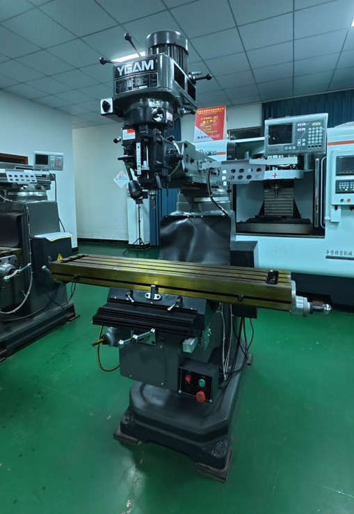
The ASIATOOLS F4 turret milling machine product page lists a digital readout and maximum axis travels of 760 mm in X, 350 mm in Y, and 350 mm in Z. Those figures apply to the listed model. Check the exact machine configuration and options before ordering.
Check the datum again after a setup change. Do not assume the old coordinate reference is still right if the workpiece, fixture, or orientation has changed.
Choosing a Turret Milling Machine?
Share your part size, machining operations, positioning needs, and accuracy requirements to discuss which machine configuration may fit the job.
Discuss Your Machine Requirements6. Standardize Cutters and Cutting Data
For repeat jobs, note the cutter type and diameter, holder, insert details where relevant, operation, and approved cutting conditions.
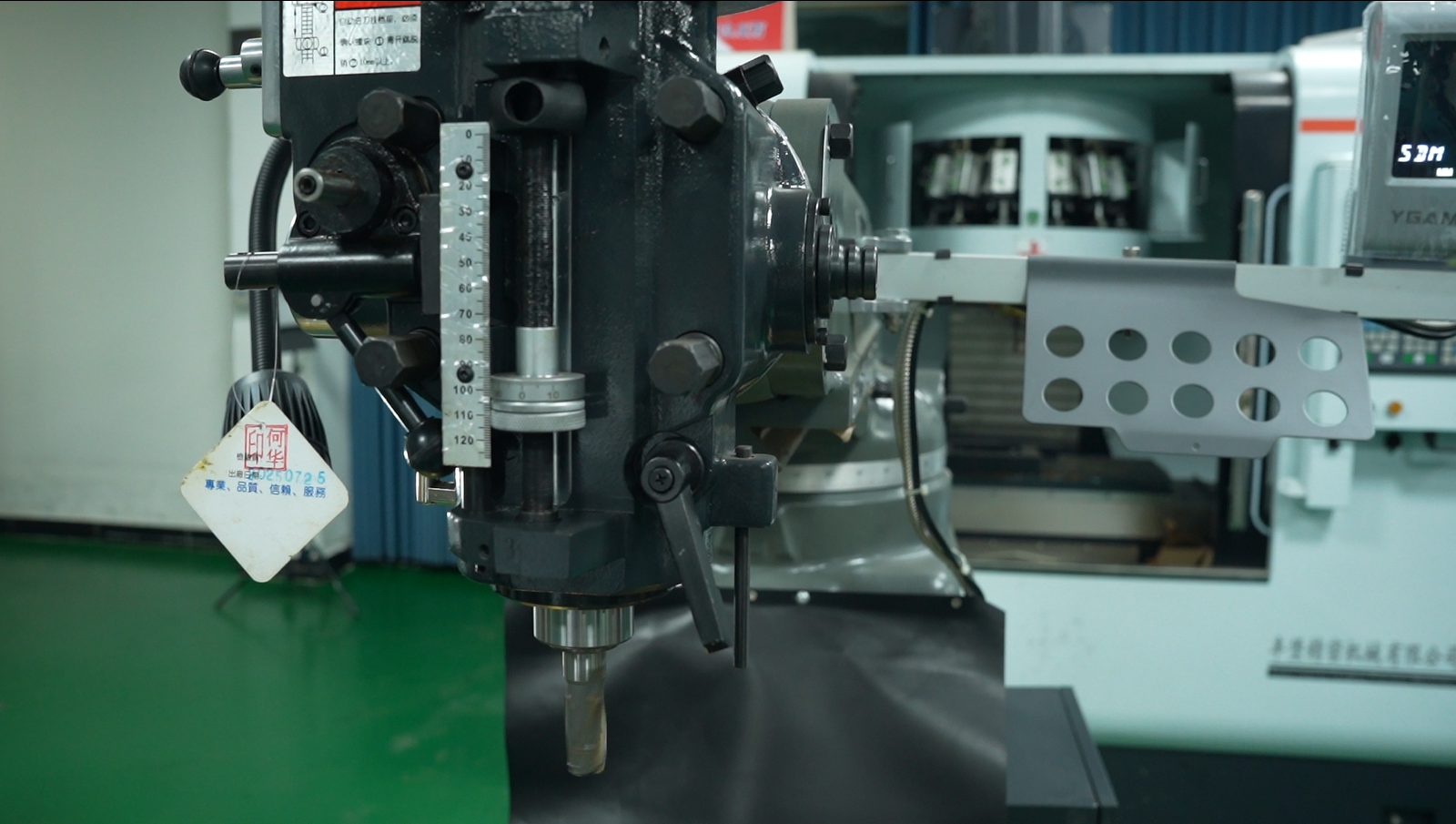
Choose cutting conditions using the tool maker's data, the material, cutter geometry, machine capacity, and workholding rigidity. Check tool wear and holder fit before installing the tool.
The CNC cutting tools range provides options to review for the intended operation. Confirm that any selected tool suits the machine and the job.
Quick-change tooling can speed up frequent tool swaps, but it only makes sense if the system fits the spindle and the time saved justifies the cost. Check rigidity and runout requirements too. If tool changes are rare, better organization may be enough.
7. Use Setup Sheets and Group Similar Jobs
For each repeat job, record the part number, drawing revision, material, workholding arrangement, datum method, tooling, cutting conditions, critical dimensions, and first-piece checks.
Add a photo if the vise orientation or stop position is hard to explain. Update the sheet when the drawing, tooling, or machining method changes.
When deadlines allow, run jobs together if they share fixtures, cutters, and setup steps. A University of Rhode Island master's thesis examined six changeovers on vertical CNC milling machines and reported fewer tool and fixture changes when jobs were grouped around shared tooling and fixtures.[2]
Do not group parts just because they look alike. Their materials, clamping needs, machining conditions, or inspection requirements may differ.
8. Cut Down First-Part Corrections Without Skipping Inspection
Before cutting, check the drawing revision, workpiece seating, clamping, tooling, datum, coordinates, and cutter clearance. Have the required gauges ready before the first part is machined.
Check every critical feature listed on the drawing or inspection plan. For a drilled part, that may mean checking hole diameter, position, and depth, not just the overall size.
If a dimension is out, find the cause before changing the setup. Depending on the problem, check the datum, workpiece movement, backlash, tool deflection, and cutting conditions.
Keep the required first-piece checks in place. A faster setup is no win if it creates more scrap or rework.
9. Keep the Machine and Workholding in Good Condition
Clean the table and T-slots before fitting fixtures. Check vise jaws, locating surfaces, clamps, toolholders, and spindle interfaces for damage or debris.
Follow the machine maker's maintenance schedule for lubrication, axis movement, backlash checks, and locking mechanisms. If alignment keeps changing between setups, check the machine and workholding before adding more manual corrections.
10. Keep Safety Checks in the Setup Process
OSHA's machine-guarding guidance identifies milling machines as equipment that generally needs point-of-operation guarding.[3]
Stop the machine and follow the manufacturer's safe setup procedure before changing workpieces or adjusting fixtures. Use lockout/tagout when required for servicing or hazardous-energy exposure. Keep guards working, secure the workpiece before cutting, and remove chips with suitable tools rather than bare hands.
Never save time by bypassing guards or rushing the clamping checks.
11. Work Out the Potential Capacity Gain
Use this formula to estimate the machine time recovered:
Monthly machine capacity recovered = Minutes saved per changeover × Monthly changeovers ÷ 60
Here is an example using a 45-minute starting point, a 30-minute target, four changeovers per day, and 20 working days per month. These are assumed values for the calculation, not measured shop data or industry averages.
| Measure | Calculation | Result |
|---|---|---|
| Time saved per changeover | 45 − 30 | 15 minutes |
| Monthly changeovers | 4 × 20 | 80 |
| Daily capacity recovered | 15 × 4 | 60 minutes |
| Monthly capacity recovered | 15 × 80 ÷ 60 | 20 hours |
If the shop achieves that 15-minute reduction across all 80 changeovers, it recovers 20 hours of machine time in the month. Replace the example inputs with actual records before using the figure to make an investment decision.
More available machine time does not automatically mean lower labor costs or more revenue. There must be work to run, and preparation done before changeover still takes operator time.
12. Check Whether the Changes Work
- Record setup times for comparable jobs.
- Change one thing, such as tool preparation or vise alignment.
- Measure the same jobs again using the same timing method.
- Compare downtime, preparation labor, first-piece acceptance, and scrap or rework.
- Update the setup sheet if the improvement holds up and quality stays on target.
Keep changes that reduce downtime without adding too much preparation work or causing quality problems. Buy extra equipment only when the measured saving makes the cost worthwhile.
Conclusion
Start with tool preparation, repeatable workholding, and a clear datum-setting method. Check the time saved and first-piece quality against real production records before spending money on a DRO, quick-change tooling, or dedicated fixtures.
Discuss Your Setup and Tooling Needs
Share your part drawing, material, machining operations, and current setup method to discuss machine specifications or tooling options for your production needs.
Submit Your Requirements