

The difference is what travels. A fixed-column machine carries the workpiece past a stationary spindle, and a moving-column machine carries the column and headstock past a stationary workpiece. That one choice sets the part ceiling at 6.2 t against 25 t, and the price at 1.5 to 2.5 times.
Switch when a single part tops 10 tonnes, one pass runs past 8 m, or the head needs more than 1.5 m of vertical travel. Meet none of them and the fixed-column machine does the same work for 33% to 60% less.
The 600,000 yuan gap at 8 m of travel works out at 240 yuan a day over 10 years and 250 working days. Setup savings return 150 yuan a day, so changing the setup method alone takes 16 years to pay it back.
On a 12 m machine, the standard thermal test covers 2,000 mm of it. How the other 10 m of drift gets measured, how often, and how much is allowed belongs in the contract. Nothing in the standard does that part for you.
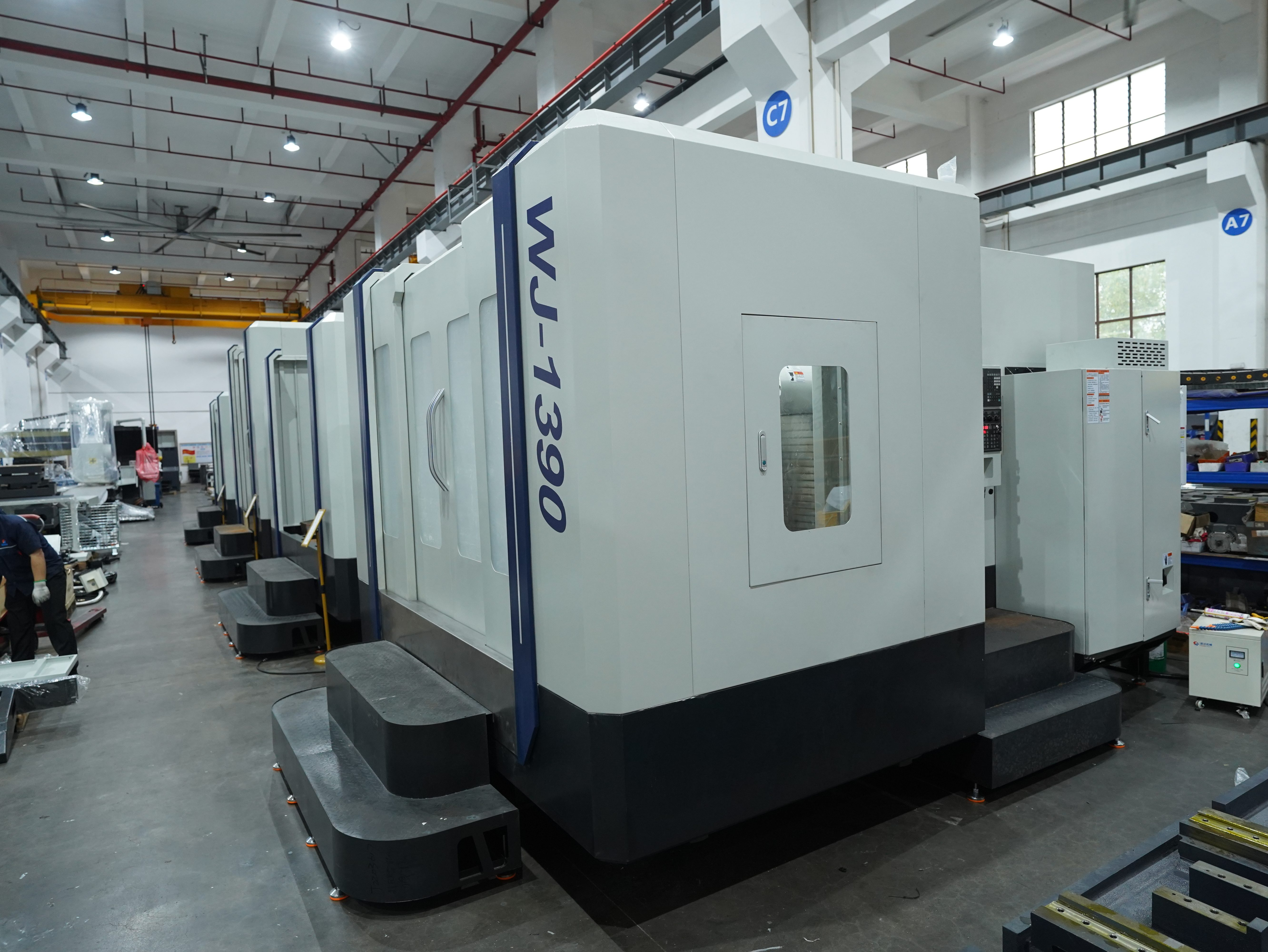
How They Differ
Fixed Column, Moving Table
ISO 3070-1:2007 covers the family of horizontal boring and milling machines with a fixed column and a moving table. The third edition runs to 51 pages and was published in December 2007.[1]
The standard splits the machine into 5 linear motions. Table feed takes Z and X. Headstock travel is Y, the boring bar or ram moves axially in W, and a facing head adds a radial slide U.[1]
Table travel usually runs 1.5 to 4 m, and spindle power sits at 7.5 to 22 kW with a 125 to 500 mm cutter. Rapids run 20 to 40 m/min on the lighter machines in this class and 2 to 6 m/min on heavy mold-base mills. One cast wall, 25 to 40 mm thick, sits between the cutter and the foundation.
A current build in this class carries a 2,500 × 1,200 mm table, a 6 t load rating and an 11 kW spindle driving a 250 mm cutter, with X and Y rapids of 5 and 2 m/min. The geometry matches a single-column horizontal face milling machine rated for 2,100 mm of machining length.
Bed and column are HT300-class grey iron at around 300 MPa tensile. The castings in a 22 t machine come to 17 or 18 t. On 2 shifts of heavy cutting the bed ways take the wear. Hardened ways with Turcite need re-grinding every 5 to 8 years, and each re-grind plus scraping costs 7 to 15 days of downtime.
Whether a part fits comes down to 3 dimensions, spindle nose to table top, spindle centreline to column ways, and T-slot pitch. Face milling usually means a table 800 to 1,600 mm wide. Slot pitch runs 160 or 200 mm.
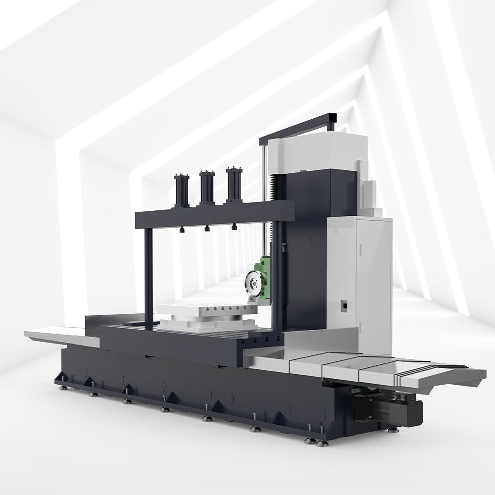
Moving Column, Fixed Table
ISO 3070-2:2016 covers the floor-type machine, where the column travels along the bed and the table stands still. The fourth edition runs to 53 pages. Column travel is X along the bed, usually 6 to 20 m, the headstock rides in Y, the ram moves in Z, and the boring bar adds W.[2]
Y travel runs 1 to 3 m. Spindle power often reaches 15 to 45 kW. Speeds run 30 to 3,000 rpm, and the cutter is 125 to 500 mm.
ISO 3070-2 also lists the universal heads you can hang on the machine. Fixed and indexable heads, a 45° mechanical indexing head, a 45° continuous indexing head, and a swivel head with 2 NC rotary axes at right angles all appear there.[2]
Most machines also carry 1 to 3 table sections R that slide along the spindle axis. A table B turns about the vertical axis, with resolution commonly reaching 0.001°.[2]
The movable-column version of the same machine trades 1 t of table load for a wider 1,400 mm table and a third rapid axis. You can see both layouts on the same horizontal face milling platform. Comparing both layouts first beats assuming the two choices sit in different size classes.
Four spindle numbers need settling early. Taper choice is BT50 or HSK-A100. Rated torque runs 200 to 800 N·m, and drawbar force runs 15 to 25 kN. Front bearing bore runs 70 to 130 mm. A 12 to 20 t weldment, pump housing or frame then gets set and dialled in once.
How the Cost Splits
| Item | Fixed column | Moving column |
|---|---|---|
| What moves | Workpiece and table | Column and headstock |
| Moving mass | Part weight plus table weight | Column assembly 8 to 30 t |
| What the drive fights | Long screw sag, accumulated thermal growth | Column overturning moment, twin-drive sync |
| Load rating basis | Per square metre, tables usually 4 to 20 t | Fixed table total tonnage, from 10 to 50 t |
| Rapid traverse | 2 to 40 m/min | 10 to 24 m/min |
| Spindle power step | 7.5 to 22 kW | 15 to 45 kW |
| Headstock Y travel | Column is fixed, Y can reach 2.5 m | Column moves, more Y means more overhang |
| Faces in one setup | Rotary table or multiple spindles | Column travelling around plus a pallet changer |
| Floor space | Tight on short travel, long travel needs room for the part and the stroke | Leaves a column corridor along the bed |
The Dividing Line
| Check | Fixed-column norm | Time to switch |
|---|---|---|
| Part weight | Rated per square metre, no whole-machine limit | A single part over 10 t, or over the rated figure times table area |
| Single-pass travel | 4 to 6 m is where a single ball screw tops out | Past 8 m, or 4 to 8 m with a full-stroke accuracy callout |
| Headstock Y travel | Y usually 1 to 2.5 m | 1.5 m or more, with heavy cutting |
| Item | Fixed column | Moving column |
|---|---|---|
| Table or fixed platen | 1,250 × 2,500 mm | 1,600 × 3,000 mm |
| X and Y travel | 2,600 / 1,200 mm | 8,000 / 1,800 mm |
| Spindle power and speed | 15 kW / 50 to 2,000 rpm | 30 kW / 30 to 1,500 rpm |
| Rapid traverse | 24 m/min | 16 m/min |
| Part ceiling | 6.2 t | 25 t |
| Machine weight | 22 t | 48 t |
| Floor space | about 45 m² | about 75 m² |
| Machine price | baseline | 1.5 to 2.5 times |
Load ratings are quoted per square metre. Multiply by the table area to get the ceiling. This fixed-column machine is rated 2 t/m² on a 3.1 m² table, for a 6.2 t ceiling. A moving-column machine quotes the fixed platen's total tonnage, so nothing gets multiplied.
Tables come in 4 sizes, 800 × 1,600, 1,000 × 2,000, 1,250 × 2,500 and 1,600 × 3,000 mm. X travel runs 2,000, 2,600, 4,000, 6,000, 8,000 and 12,000 mm. Y travel runs 800, 1,000, 1,200, 1,500 and 1,800 mm.
Spindle power comes in 5 ratings, 11, 15, 22, 30 and 45 kW. Machine weight runs 12, 22, 28, 40 and 48 t. Rapids run 2, 5, 16, 20, 24 and 40 m/min.
A moving table pays 2 bills before it carries anything. One is the inertia of pushing 10 to 20 t, and the other is friction and wear on the ways. Drop the rapid from 40 to 20 m/min and the mass you can move comes back by 20% to 30%. Past 10 t the table gets re-rated at 2 to 3 t/m². The table and ways on the same size machine usually go up 1 or 2 steps.
Ball screws 40 to 80 mm in diameter stop being practical around 4 to 6 m of travel. After that, builders move to rack and pinion with twin-motor preload at module 4 to 8. The changeover point is 8 m, and beds past 12 m are rack only.
Feeds need 3 figures, rapid 2 to 40 m/min, cutting feed 1 to 6,000 mm/min, and acceleration 1 to 3 m/s². A twin-drive machine also needs its preload method and its backlash stated.
The fixed-column machine at 6 to 8 m of travel is a shelf item, and at that travel the discount runs 30% to 50%. Once a job needs more than 3 faces in a single setup, a rotary table starts earning its place. A 5 to 30 t rotary table usually adds 10% to 20% to the machine price.
Setup count is not decided by the column alone. A duplex milling machine cuts 2 opposite faces in one pass and pulls work out of the cycle without changing the column layout at all.
Moving-column assemblies weigh 8 to 30 t. Centre of gravity sits above 2 m. Past 1.5 m of Y travel you add 2 to 5 t of counterweight. Every extra 500 mm of headstock reach pushes the counterweight and the column section up another step.
Typical face-milling work is valve bodies, pump housings, connecting flanges and frame faces. Widths run 100 to 800 mm. Stock runs 2 to 6 mm per side, with a 60 to 240 second cycle. Fixed-column machines mostly run 300 to 800 mm square housings and flanges. Moving-column machines run 6 to 12 m frames and ship sections.
Where Rigidity Comes From
On a fixed-column machine the cutting force never passes through a moving column. Little on the machine is left to shake. Roughing suits it at 3 to 6 mm depth. Feed per tooth sits at 0.1 to 0.3 mm. Width of cut covers 60% to 80% of the cutter diameter.
Cast iron sits in the HB180 to 250 band. Carbon steel comes in at HB150 to 200. Both cut easily. Austenitic stainless lands at HB150 to 190 and martensitic stainless at HB200 to 300. The austenitic grade wants the feed pulled back near 0.1 mm per tooth.
A 250 mm cutter at 150 m/min in cast iron works out to 190 rpm. Swap in a 500 mm cutter at the same 150 m/min and the speed drops to 95 rpm.
Run the numbers and that cut feeds at 304 mm/min and removes about 243 cm³/min. Cast iron takes 2,000 to 2,500 N/mm² of specific cutting force. Net spindle power lands at 8 to 12 kW. The 15 kW fixed-column machine in the spec table has just enough.
A 20 t column assembly running 8 m of travel at 16 m/min over 2 shifts of 16 hours covers about 960 round trips a day, or more than 1,900 reversals. Every reversal lands on the ways like a truck hitting a pothole. Under that duty the column squareness and X straightness need re-checking every 6 to 12 months. Each check costs 4 to 8 hours of downtime.
X ways run 300 to 500 mm wide with ribs every 300 to 500 mm. The hardened face covers 20% to 33% of the bed width.
Past a 3 m plate the structure has to change rather than grow. Plates in the 1,800 × 3,000 mm class at up to 14 t sit on the fixed table of a CNC gantry milling machine with a 22 kW BT50 spindle and box ways on Z. A 14 t load is what changes the machine drawing.
Take the finishing cut down to 0.3 to 0.8 mm and the moving-column machine holds Ra 1.6 to 3.2 µm. The fixed-column machine holds Ra 3.2 µm on the same cut.
Accuracy and Thermal Drift
The Test Line-Up
Geometric accuracy follows ISO 230-1:2012, measured unloaded or quasi-static. Straightness, flatness, parallelism, squareness, coaxiality, positioning and static stiffness with hysteresis all fall under it. The third edition runs to 160 pages.[3]
Any single linear axis carries 6 error motions of its own, scale, straightness in 2 directions, pitch, roll and yaw. Those 6 error motions sit behind the long list, since every extra metre of travel adds one more axis to map.[4]
Positioning accuracy and repeatability follow ISO 230-2:2014, measured by repeating at each target. Positioning accuracy, repeatability and reversal difference all come out of that. The fourth edition totals 43 pages. Type tests, acceptance tests, comparison tests, periodic checks and machine compensation make up its 5 uses.[5]
Spindles follow ISO 230-7:2015, 72 pages. Spindle units, indexing heads and rotary or tilting tables all count as axes of rotation. Axis error motion and speed-induced drift sit inside this standard. Thermal drift goes to ISO 230-3:2020.[6]
Catalogue these as intra-axis errors, inter-axis errors and volumetric errors, because that is how calibration literature separates them. Measurement, modelling and compensation each have a different cost and complexity, and picking all 3 from the same tier is where budgets go wrong.[7]
Taper choice tracks the power step. BT40 usually goes with 7.5 to 11 kW, BT50 with 15 to 22 kW and HSK-A100 with 30 to 45 kW. The cutters behind them run 125 to 160, 200 to 315 and 400 to 500 mm.
Thermal behaviour follows ISO 230-3:2020, third edition, 50 pages, and it carries 4 tests. Ambient temperature variation, spindle rotation, linear axis motion and rotation of rotating parts make up the set.[8]
Why Long Travel Hurts More
The chapter on linear axis thermal distortion in ISO 230-3:2020 only covers axes up to 2,000 mm of travel. Beyond that length, the standard tells you to pick a 2,000 mm representative length inside the working range and test that.[8]
On a 12 m machine the standard thermal test covers 2 m of it. The other 10 m of drift stays with the buyer. How it gets measured, how many runs, and what is allowed all belong in the contract.
A spindle run for 2 to 4 hours grows 20 to 60 µm axially. The machine needs 2 to 6 hours to reach thermal balance. Wait 3 hours before you record anything.
Linear axes grow too. Steel moves 11.5 µm per metre per degree C. A 6 m bed warmed by 3 °C grows 0.2 mm. Most machines hold a full-stroke positioning accuracy an order of magnitude tighter.
Axial drift of 0.05 mm on a face is already past the 0.046 mm H7 tolerance on a φ200 fit, and those limit deviations come straight out of the ISO 286 tables rather than the machine builder's datasheet.[9]
Face runout is an acceptance line at 0.01 mm standard grade and 0.005 mm precision grade. On a face mill that number matters more than it does on a boring machine, where radial runout draws the attention.
Which Accuracy Basis
Quotes often come per 300 mm. The same machine can be quoted at 0.008 mm on the 300 mm basis. Over the full 6 m the figure is 0.02 mm, a factor of 2.5. Accumulated pitch error plus thermal growth adds the extra 0.012 mm.
Full-stroke positioning accuracy runs 0.05, 0.03, 0.02, 0.015 and 0.008 mm against 2, 4, 6, 8 and 12 m of travel. Repeatability in the same step is 0.02, 0.015, 0.01, 0.008 and 0.005 mm. The ratio sits at roughly one third to two thirds of the positioning figure.
Which basis you sign can swing the price 10% to 20%. Travel gets fixed first, then the accuracy step. Where the scale sits decides the result too. A 3 m screw warmed by 1 °C grows about 35 µm. Full closed loop measures the moving member and cancels that 35 µm. Semi closed loop reads the motor encoder and has to carry all of it.
Floor Space and Loading
A 2,600 mm travel fixed-column machine takes about 45 m² of floor. An 8,000 mm moving-column machine takes about 75 m². Match the two on 8 m of travel and the fixed-column machine needs roughly three tenths more floor, a difference of 15 to 25 m² per machine.
A moving-column bed runs 6 to 20 m with 20 to 40 foundation bolts. Each bolt carries 1.2 to 2.4 t. Concrete runs C25 or better, and grout goes 500 to 1,500 mm deep.
An 8 m moving-column machine measures roughly 12,000 × 4,500 × 3,800 mm and weighs 48 t. Shipping splits into 2 or 3 pieces, with 15 to 30 days of on-site assembly.
Long plates get cut to length before they ever reach the mill, and a flat-plate circular saw does that in one pass rather than 3 roughing cuts on the machine.
When the part does not move, you set it and dial it in once, and a pallet changer or a robot loads while the cutter is still in the metal. One operator runs 2 or 3 machines, and daily output rises 15% to 25%. When the table carries the part, the loading aisle sits under the workpiece. A part over 10 t takes 10 to 20 minutes of crane time to land, and the spindle sits idle for all of it.
Price and Lifetime Cost
Driving an 8 to 30 t column assembly needs bigger ways, preloaded rack and pinion, and a longer bed casting. Every extra metre of bed adds 2 to 4 t of casting. Machines past 8 m of travel usually twin-drive X, with a 7.5 to 15 kW motor on each side.
A 12 to 20 t casting takes 1 to 2 hours of crane time and dialling. Over 250 working days with one setup saved a day, that is 250 to 500 hours a year. At 80 to 150 yuan an hour the saving reaches 20,000 to 75,000 yuan a year.
Payback tracks the machine rate as much as the hours. At 150 yuan an hour the same 1.5 hour saving reaches 225 yuan a day, and payback drops from 16 years to about 11.
Rework from a single joint mismatch costs 20,000 yuan of material plus 16 hours of downtime at 150 yuan an hour. The total reaches 22,400 yuan, or 93 days of that 240 yuan. Rework and scrap are where the premium has to earn out.
Under 2 shifts of heavy cutting, ways, rack and screws are consumables. Accuracy checks are annual, and a full-stroke run takes 2 to 4 hours on a long axis. Way oil changes every 250 hours, filters at 500 hours, and rack and slide grease at 1,000 hours. Spindle bearings last 20,000 to 30,000 hours.
A 250 mm 8-tooth cutter runs 60 to 120 yuan a tip. One set of 8 lands at 480 to 960 yuan. With 4 edges per tip and 2 to 4 hours of life per set, the cost works out at 3 to 12 yuan on a 90 second part.
At a 90 second cycle and 100 yuan an hour, machine time is 2.5 yuan a part. Tooling, labour and depreciation add 5 to 14 yuan on top, for 7.5 to 16.5 yuan a part. Stopping the machine for an hour at 40 parts an hour costs 300 to 660 yuan.
At 4,000 hours a year and 65% to 80% spindle utilisation, that is 2,600 to 3,200 hours of actual cutting. Annual output runs 104,000 to 128,000 parts.
Enquiry Sheet Checklist
The material line matters as much as the machine line. P20 and 1.2311 arrive pre-hardened at 28 to 32 HRC, while 45#, H13 and D2 do not, and that changes the depth of cut you can quote. Standard mold steel blocks cover 1045, 1.2311, 1.2343, 1.2344, 1.2312, 1.2738, 1.2083 and 1.2085, so the grade list is usually longer than the machine list.
| Item | What to state |
|---|---|
| Workpiece | Material, single-part weight in tonnes, envelope, largest face to be milled |
| Travel | X single pass, Y, Z, and whether full-stroke accuracy is required |
| Positioning accuracy | Full-stroke positioning and repeatability, tested to ISO 230-2 |
| Geometric accuracy | Straightness, flatness, parallelism and squareness tolerances over full length, tested to ISO 230-1 |
| Thermal behaviour | Spindle run time and axial growth, whether compensation is fitted, residual after compensation |
| Spindle | Taper, rated torque, drawbar force, bearing bore, cutter diameter, speed range, face runout |
| Feed | Rapid and cutting feed range, drive type, twin-drive preload, servo power |
| Load rating | Per square metre or fixed table total, with the basis stated |
| Clearances | Spindle nose to table, spindle centreline to column, T-slot pitch |
| Services | 380 V 50 Hz supply, coolant flow and concentration, chip handling, IP rating |
| Envelope and shipping | Overall size, machine weight, lifting points, number of pieces, on-site assembly time |
| Lubrication and wear parts | Way oil and grease intervals, filter intervals, spindle bearing life |
| Electrical load | Total connected load, voltage and frequency, air pressure, earthing and lighting |
| Testing | Factory test report, standard accessories, re-check interval and cost |
| Safety | Guard and safety function list to ISO 16090-1, brake on gravity-loaded axes |
| Service | Installation and commissioning time, warranty, spare parts list and lead time |
Testing on Arrival
Geometric accuracy gets measured unloaded or quasi-static and after the machine reaches thermal balance. Straightness, flatness, parallelism, squareness and coaxiality make up the list. Room temperature gets logged to 0.5 °C.[3]
Positioning points have to cover the full stroke, ends and middle. A 6 m axis needs at least 15 to 25 targets. Each target takes 5 runs each way. A full round comes to 150 to 250 measurements.[5]
The spindle gets checked for axis error motion and speed-induced drift. Face runout gets dialled on the nose and the taper to 0.001 mm resolution. Run 3 speed steps, 0 to 500, 500 to 1,500 and 1,500 to 3,000 rpm. Hold each one 10 to 15 minutes before you record.[6]
Thermal testing splits in two, with the spindle run to thermal balance. The linear axis runs back and forth while the drift gets logged. Axes past 2,000 mm of travel get tested over a 2,000 mm representative length.[8]
Static geometry is only half the acceptance. A machining test on a finished test piece carries the errors that geometry checks cannot see, and ISO 230-12:2022 sets out how those tests are defined and evaluated, thermal influence included.[10]
ISO 8688-1:1989 covers tool life testing for carbide face mills in steel and cast iron. Wear is the failure criterion, and the standard runs 27 pages. Insert grades usually read P25, K20 or P40 class.[11]
Industry speeds land at 100 to 200 m/min in cast iron. Carbon steel runs 120 to 250, and aluminium 300 to 1,000.
Watching the cutting test on your own material before the machine ships beats reading a brochure. Face milling at 2 mm depth in 45# steel and duplex milling of P20 mold steel both appear in the published machine demonstrations, and watching either one tells you more about duty than a spindle power figure does.
Feed runs 0.1 to 0.3 mm per tooth, with 0.3 to 0.8 mm of finishing stock. The wear land calls for a change at 0.3 to 0.6 mm. Spindle motors take 380 V 50 Hz. Coolant pumps move 30 to 100 L/min at 2 to 6 MPa, and chip conveyors shift 100 to 200 kg/h. The enclosure is at least IP54.
A laser interferometer resolves to 0.001 µm and a dial gauge reads to 0.001 mm. Ambient temperature sits around 20 °C with no more than 1 °C of change per hour. Lead times usually read 10 to 20 working days to install and commission. Training runs 3 to 5 days. Warranty runs 12 to 24 months, and common spares land in 4 to 8 weeks.
Where flatness has to survive past milling, a CNC surface grinding machine works the same plate envelope after the mill. The load budget changes once a chuck and fixtures are added, and a worked example on a 1,200 × 2,000 × 120 mm plate shows how much.
- Hydraulic clamping pressure 4 to 8 MPa, compressed air 0.5 to 0.8 MPa.
- Coolant concentration 5% to 10%, filtration 20 to 50 µm.
- Spindle taper runout 0.005 mm, face runout 0.01 mm standard and 0.005 mm precision, dynamic balance G2.5, taper BT50 or HSK-A100.
- Part face flatness 0.02 to 0.05 mm, surface roughness Ra 1.6 to 6.3 µm.
- Spindle 7.5 to 45 kW, X axis 15 to 30 kW, Y axis 7.5 to 11 kW.
- Hydraulic unit 3 to 7.5 kW and chip and coolant 2 to 5 kW, 35 to 100 kW total, or 45 to 125 kVA.
- Cabinet to IP54, earthing under 4 Ω, work lights 300 to 500 lux, 380 V 50 Hz supply.
Safety and Compliance
ISO 16090-1:2022 sets the safety baseline for milling machines and machining centres. The second edition runs to 155 pages, with a corrected version issued in October 2023. This standard sorts machines into 4 groups by how much CNC they carry. Coverage runs from manually operated boring and milling machines through limited-CNC machines and CNC mills to special-purpose machines and transfer lines.[12]
8 requirement groups matter for selection. Guards and impact testing, control system safety functions, coolant and chip ejection protection, noise declaration, flammable coolant and dust, minimum quantity lubrication, ergonomics and gravity-loaded axes cover the ground.
Operators see 75 to 85 dB and work lights need 300 to 500 lux. Ambient runs 5 to 40 °C. The 85 dB figure is not arbitrary, since the recommended occupational exposure limit sits at 85 dBA over an 8 hour shift.[13] Altitude stays below 1,000 m, and humidity stays under 80% without condensation.
Safety items on a moving-column machine cluster on the column. As a gravity-loaded axis it needs a brake that holds on power loss. The bed runs 6 to 20 m, so walkways and fencing have to cover the whole column travel. On a fixed-column machine the cluster sits at both ends of the table stroke. A spindle takes 5 to 10 seconds to stop from 3,000 rpm, and the pallet change has to wait for it.
The buying action is to make the supplier hand over a risk assessment and a safety function list to ISO 12100. Every item needs a verification method against it. One blanket declaration of conformity is not enough.
Common Questions
Is a Moving Column More Accurate
Both machines can hold 0.02 mm over the full stroke if they carry scales and thermal compensation. The difference shows up 2 years in. By then the fixed-column machine is usually still inside 0.03 mm, and the moving-column machine needs its regular re-checks to stay there.
Whether Travel Settles It
Order books answer this faster. If more than 60% of your annual parts run over 6 m long, the extra money for a moving column earns out. An 8 m fixed-column machine is stocked domestically and ships in 1 to 3 months.
Checking a Used Machine
3 documents come first. They are the full-stroke accuracy report, the way re-grinding or Turcite record, and when the rack and screws were last changed. On a 10 year old machine, more than 2 re-grinds means you recalculate the accuracy decay.
Before the Order Goes Out
Put 3 figures in the contract, full-stroke positioning accuracy at 0.02 mm, repeatability at 0.01 mm, and spindle face runout at 0.01 mm. The machine ships with 4 documents.
- Full-stroke accuracy report.
- Spindle axial growth record taken after thermal balance.
- Cutting test record with the 250 mm cutter and 8 teeth, cutting speed and feed per tooth both stated.
- For machines past 2 m of travel, a full-stroke drift test plan.
Then write the heaviest part, the longest part and the number of faces per setup onto 1 page. Add those 3 figures. Send the same sheet to 2 or 3 builders so the quotes can be compared line for line.
Send the one-page sheet
Two numbers decide the layout, your heaviest part and your longest pass. Send those with the drawing, the steel grade and the tolerance callouts, and the reply comes back within 24 hours as a quote that names the machine, the setup and the machining method line by line, written by the engineers who run the same machines on their own production floor.
Request a Factory-Direct QuotePrepared by engineers, in English, against your own print. No obligation.
Sources
The 13 numbered sources are public standards abstracts, national metrology publications and one peer-reviewed review paper, so you can check each one yourself. Everything else carrying "usually" or "often" is industry convention drawn from catalogues and shop-floor practice.
The figures work for scale only, not as a standard limit. Machine price multiples and gaps cover the machine alone, not foundation, installation, tooling or training.
- ISO 3070-1:2007, Test conditions for boring and milling machines with horizontal spindle, Part 1, machines with fixed column and movable table
- ISO 3070-2:2016, Test conditions for boring and milling machines with horizontal spindle, Part 2, machines with movable column along the X-axis (floor type)
- ISO 230-1:2012, Test code for machine tools, Part 1, geometric accuracy of machines operating under no-load or quasi-static conditions
- National Institute of Standards and Technology, Three Dimensional Metrology, NIST Special Publication 958
- ISO 230-2:2014, Test code for machine tools, Part 2, determination of accuracy and repeatability of positioning of numerically controlled axes
- ISO 230-7:2015, Test code for machine tools, Part 7, geometric accuracy of axes of rotation
- Gao, Ibaraki, Donmez et al., Machine tool calibration: Measurement, modeling, and compensation of machine tool errors, International Journal of Machine Tools and Manufacture, vol. 187, 2023
- ISO 230-3:2020, Test code for machine tools, Part 3, determination of thermal effects
- ISO 286-2:2010, Geometrical product specifications (GPS), ISO code system for tolerances on linear sizes, Part 2, tables of standard tolerance classes and limit deviations for holes and shafts
- ISO 230-12:2022, Test code for machine tools, Part 12, accuracy of finished test pieces
- ISO 8688-1:1989, Tool life testing in milling, Part 1, face milling
- ISO 16090-1:2022, Machine tools safety, machining centres, milling machines, transfer machines, Part 1, safety requirements
- U.S. National Institute for Occupational Safety and Health (NIOSH), Noise-Induced Hearing Loss, recommended exposure limit 85 dBA over an 8-hour shift