

A fixed-table moving-column layout makes sense when a heavy or long workpiece is better left stationary during the main travel. A moving-table machine makes sense when the whole setup fits its load and travel limits and gives you the lower production cost. A 900 kg casting plus 350 kg of fixtures is already a 1,250 kg payload, so judge the machine on the full setup, not the casting alone.
Check Which Axes Move the Workpiece
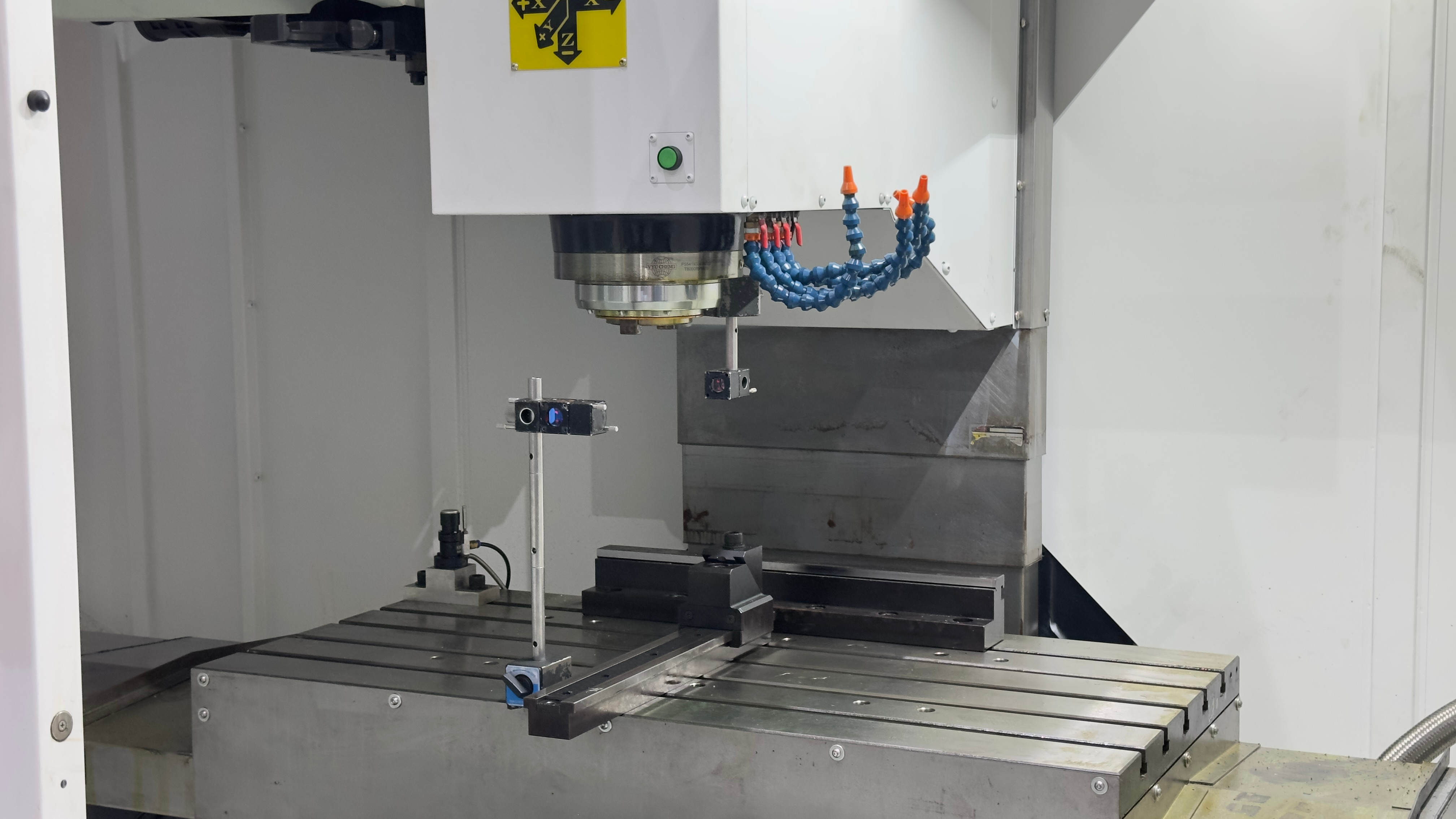
On a typical moving-table vertical machining center, the table carries the workpiece in X and Y while the spindle head moves in Z. A moving-column machine shifts the column along at least one axis, though the table may still move or rotate on other axes.
The WJ-1065 horizontal machining center, for example, uses a moving-column structure and lists X/Y/Z travels of 1,000/650/400 mm. For your part, those travel numbers matter more than the label on the machine.
Moving Column vs Moving Table: What Changes Your Decision?
| Your production requirement | Moving-column consideration | Moving-table consideration |
|---|---|---|
| Heavy casting or tall fixture | A fixed workholding surface avoids translating the payload on the column axis. | Check payload, centre of gravity, and the permitted motion with that load. |
| Long fabrication or mold base | A long fixed bed can provide support along the part. | Check full table movement, support positions, and usable cutting travel. |
| Frequent changes in part weight | Payload changes do not add moving mass to an axis carried entirely by the column. | Test representative loads because the table axes carry the changing payload. |
| Heavy roughing | Test at the required head height and ram extension, where applicable. | Test at the required table position with the production fixture. |
| Long loading and setup time | Investigate separately guarded work zones if available. | Investigate pallet or workpiece changers if available. |
| Tight dimensions and flatness | Require loaded cutting and thermal checks. | Require the same checks under comparable conditions. |
Add the Fixture Weight Before Comparing Table Capacity
Use the heaviest unfinished part, not the finished part weight. Then add everything the table carries: fixture plates, supports, clamps, angle plates, and rotary equipment.
Here is a simple example:
| Item | Weight |
|---|---|
| Unfinished casting | 900 kg |
| Fixture plate and supports | 280 kg |
| Clamps and accessories | 70 kg |
| Total payload | 1,250 kg |
On a hypothetical machine rated for 1,500 kg, that setup uses 83.3% of the stated capacity and leaves 250 kg on paper. That does not automatically mean the loading condition is acceptable.
A tall fixture or a casting sitting near one end of the table loads the machine differently from a centered, evenly supported part. Support points and center of gravity matter.
A fixed table has limits too. Check whether the rating refers to total weight, weight per unit area, or a specific support arrangement.
Will the full fixture fit the machine?
Give ASIATOOLS the casting weight, fixture weight, overall dimensions, and support positions. The setup can then be checked for table load and machining access.
Request a Load and Fixture ReviewCheck Cutting Travel and Vertical Clearance
Follow the tool-center path, including entry and exit moves. The nominal part length is not always the travel you actually need.
For example, a 2,400 mm feature span plus 100 mm of tool-center travel at each end needs 2,600 mm of usable travel. A 2,500 mm axis is 100 mm short for that process.
The real allowance depends on cutter diameter, entry strategy, clamps, and feature position.
Vertical space works the same way. A 400 mm-high part on a 150 mm fixture already uses 550 mm above the table. The tool, approach clearance, retract move, and tool change still need room. That is why spindle-nose-to-table distance matters as much as Z travel.
If a long mold base mainly needs broad side faces milled, compare it with a horizontal face milling configuration. That is a different job from a machining center that also has to drill, pocket, and change tools automatically.
Choose Moving Column When Stationary Workholding Removes a Constraint
A fixed-table moving-column machine is worth looking at when a long fabrication needs support along its length or a heavy casting is awkward to move through the whole cutting stroke.
On an axis that moves only the column assembly, extra workpiece weight does not directly become extra moving mass on that axis. The column and spindle still have to accelerate, but the payload itself stays out of that motion.
That does not mean a moving-column machine is automatically faster. A large moving column can easily be slower than a compact moving table on a light-part job.
Reach matters too. A machine may cut nicely close to the spindle support and behave quite differently with a ram extended or a long tool reaching into a deep housing.
Choose Moving Table When Your Work Fits Without Extra Handling
A moving-table machine is still a very practical choice if it carries the full fixture, reaches every feature, and finishes the job without extra setups.
For example, a 180 kg component on a 120 kg fixture gives a total payload of 300 kg. If that fits comfortably inside the machine's load and travel limits, there may be no reason to complicate the layout.
Use Accuracy Reports and Finished Parts Together
ISO 230-2 describes methods for measuring positioning accuracy and repeatability on individual linear and rotary axes. That makes it useful for reading an axis test report, but one brochure figure is still not the same thing as finished-part accuracy.[1]
Look at the measurement length, approach direction, warm-up state, and whether compensation was active. A good result across 300 mm does not automatically prove a 2,000 mm feature spacing.
For an illustrative drawing dimension of 800.00 ±0.02 mm, the acceptable range is 799.98–800.02 mm. That 0.04 mm band belongs to the finished dimension; it is not a direct axis-positioning tolerance.
Finished parts matter too. ISO 10791-7 covers standard test pieces and finishing-condition cutting tests for machining centers with three to five simultaneous machining axes.[2]
For your own acceptance trial, use the critical bore spacing, flatness, or pocket geometry from the real production drawing. Also state whether the part is inspected clamped or released and how it is supported.
Check Thermal Drift During a Representative Run
A machine can look perfect in a short demo and move after hours of cutting. NIST researchers have measured micrometer-level tool-to-workpiece thermal drift, which is why thermal behavior matters when tolerances are tight.[3]
If your production cycle takes two hours, the trial should cover the actual roughing and finishing sequence. Measure important dimensions after warm-up and again later in the run.
For example, if a feature moves from 800.000 mm to 800.012 mm, the shift is 0.012 mm. With an upper limit of 800.020 mm, only 0.008 mm remains.
Compare Roughing at the Required Tool Reach
For heavy cutting, look at spindle torque at the speed you actually use. Maximum power and maximum rpm do not tell you the full story.
Keep cutters, inserts, overhang, cutting width, and depth comparable. Record tool wear along with cycle time.
For a straight milling pass, a 50 mm cutting width, 2 mm depth, and 800 mm/min feed give a nominal removal rate of 80,000 mm³/min, or 80 cm³/min. That is a geometric calculation, not a recommended cutting condition.
Count entry, exit, repositioning, and tool changes in the full cycle too.
If the cutter moves in its holder, check end mill pull-out during steel roughing before blaming the machine structure. Measure tool length before and after the test.
Compare the machines on the cut that worries you most.
Tell ASIATOOLS the material grade, stock allowance, tool reach, and required finish. Ask which configuration should be tested and what the trial should include.
Discuss Your Cutting RequirementsCheck Installed Space and Cost per Accepted Part
Machine footprint is more than the casting dimensions. Include full axis movement, open doors, electrical cabinets, coolant equipment, chip handling, maintenance space, and the crane or forklift route.
A nominal 3.1 × 3.0 m machine covers 9.3 m² before outside access is added. If the final layout becomes 4.5 × 4.0 m, you actually need 18 m². These are examples, not standard clearance requirements.
For a moving-table machine, look at the swept area of the loaded table. For a moving-column machine, look at column travel and access around each working zone.
Cost per accepted part = annual ownership and operating cost ÷ annual accepted output.
An annual cost of $120,000 across 6,000 accepted parts equals $20 per part. A second system costing $135,000 per year needs 6,750 accepted parts to reach the same $20 figure, assuming the annual cost stays the same at that output.
What to Put in the Machine Enquiry
- One typical part and one demanding part, with drawings and models.
- Material grade, hardness where relevant, unfinished weight, and stock allowance.
- Complete fixture weight, dimensions, support positions, and centre of gravity.
- Required machining faces, tool reach, and critical tolerances.
- Batch quantity, annual demand, and current loading time.
- Available installation space and handling equipment.
Request a quote around your part and production volume.
Include your largest setup, required operations, batch size, and available floor space. Ask ASIATOOLS to show the proposed machine, required options, and any process limits in the quotation.
Request a Machine Configuration QuoteFinally
Choose a fixed-table moving-column layout when keeping the workpiece still solves a load, support, or handling problem. Choose a moving-table machine when the complete setup fits and its tested production cost comes out lower. In the example above, count the full 1,250 kg payload, not just the 900 kg casting.