Tool chatter is one of the most common problems in side milling and roughing operations, especially in mold steel machining. It often appears as abnormal noise, visible vibration, unstable cutting forces, or poor surface finish. Although chatter is frequently attributed to the cutting tool, real-world machining experience shows that it is usually caused by insufficient rigidity of the entire machining system.
In side milling, cutting forces act mainly in the radial direction, making the process highly sensitive to rigidity, runout, and dynamic stability. The machine tool, spindle, toolholder, tool overhang, cutting parameters, workpiece clamping, and material properties all play a role in the formation of chatter.
1. What Causes Tool Chatter in Side Milling?
Tool chatter rarely has a single cause. In most cases, it results from multiple rigidity-related factors acting together.
1.1 Excessive Tool Overhang in Side Milling
Excessive tool overhang is one of the most common causes of tool chatter during side milling. As a general guideline in mold steel roughing, once the tool overhang exceeds three times the tool diameter, bending stiffness drops sharply.
Because side milling generates continuous lateral cutting forces, long overhang tools are more likely to deflect, oscillate, and amplify vibration. Even on rigid CNC machines, excessive overhang can quickly push the system into an unstable cutting condition.
1.2 Tool Structure and Geometry Affect Chatter Resistance
The design of the cutting tool has a direct impact on vibration behavior. In side milling and roughing operations, several structural factors increase the risk of chatter:
(a) Small-diameter tools are more sensitive to bending under lateral cutting forces.
(b) Long-neck or extended-reach tools significantly reduce overall rigidity.
(c) Standard end mills with equal pitch teeth are more prone to harmonic vibration.
Using unequal pitch or unequal helix end mills helps break vibration frequency overlap and is a proven method for reducing tool chatter in mold steel machining.
1.3 Toolholder, Collet, and Spindle Runout
Poor concentricity is another major contributor to roughing vibration. Excessive runout caused by worn collets, low-precision toolholders, or spindle wear leads to uneven chip load distribution.
This uneven loading creates periodic force variation, which is one of the main mechanisms behind regenerative chatter in side milling. Even small runout values can significantly reduce machining stability at high spindle speeds.
1.4 Cutting Parameters in an Unstable Range
Improper cutting parameter selection often triggers chatter, even when the machine and tool are rigid. Common unstable conditions include:
(a) Excessive radial depth of cut in side milling.
(b) Aggressive axial depth combined with insufficient system stiffness.
(c) Unstable feed strategies during roughing operations.
In many cases, the problem is not that the parameters are too high, but that they fall within a resonance-sensitive speed range of the machining system.
1.5 Mold Steel Material Properties
Mold steels such as H13 and P20 generate high cutting forces during roughing due to their strength and toughness. During side milling, these forces fluctuate continuously.
If spindle torque is insufficient, guideway clearance is excessive, or lubrication is poor, these force variations can easily excite tool chatter. This explains why cutting parameters that work well on softer materials may fail in mold steel machining.
1.6 Insufficient Workpiece Clamping Rigidity
Tool chatter is not always caused by the tool or spindle. Poor workpiece clamping, unstable shims, or flexible fixtures allow micro-movement during side milling.
This micro-displacement feeds back into the cutting process, creating vibration that is often misinterpreted as a tool-related issue.

2. What Are the Effects of Tool Chatter on Machining Quality?
Uncontrolled tool chatter negatively affects both surface quality and machine health. Typical consequences include:
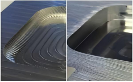
(a) Wavy surfaces and visible tool marks on machined parts.
(b) Increased rework requirements and longer machining cycles.
(c) Accelerated tool wear and unexpected tool breakage.
(d) Damage to toolholder tapers and spindle bearings.
(e) Long-term decline in overall machine tool accuracy.
In mold steel machining, ignoring chatter during roughing often leads to higher finishing costs and reduced overall productivity.

3. How to Reduce Tool Chatter in Side Milling
3.1 Minimize Tool Overhang and Improve System Rigidity
Reducing tool overhang is one of the most effective ways to control chatter. In practical machining, this includes the following actions:
(a) Use the shortest tool length required for the operation.
(b) Choose high-rigidity toolholders such as shrink-fit holders or heavy-duty collets.
(c) Select vibration-resistant or unequal-pitch end mills for mold steel roughing.
Improving stiffness at the tool end usually delivers immediate and measurable stability benefits.
3.2 Use High-Rigidity Equipment for Heavy Roughing
For large mold bases and thick steel blocks, machine rigidity becomes a limiting factor. Performing roughing operations on high-rigidity machines, such as CNC duplex milling machines, allows higher material removal rates with improved stability before finishing operations.
3.3 Adjust Spindle Speed to Avoid Resonance
If chatter occurs despite a rigid setup, adjusting spindle speed by five to ten percent upward or downward often moves the process out of the resonance zone. In many cases, this method is more effective than simply reducing feed rate or depth of cut.
3.4 Maintain Machine Tool and Clamping Stability
Stable side milling depends on good machine condition and reliable clamping. Key maintenance and setup actions include:
(a) Ensuring proper guideway lubrication.
(b) Regularly checking the spindle condition for abnormal noise or vibration.
(c) Firmly securing fixtures, pads, and workpieces.
Reducing random vibration sources significantly improves overall machining stability.
4. Conclusion: A System-Level Approach to Tool Chatter
Tool chatter in side milling is not a single-component problem. It is the result of interactions between the machine tool, cutting tool, toolholder, workpiece clamping, cutting parameters, and mold steel material properties.
The goal is not to eliminate vibration entirely, but to keep it within a stable and controllable range. By focusing on system rigidity and process optimization, most chatter problems in mold steel machining can be reduced without increasing production costs.
To learn more about our mold steel roughing solutions and machining equipment, please contact us for technical support and recommendations.