P20 pre-hardened plastic mold steel is typically supplied at about 30–36 HRC, allowing it to be machined directly without additional heat treatment and helping prevent distortion.
It is mainly used for injection molds such as automotive bumper molds, inserts, and general tooling.
For machining, carbide tools are recommended, with milling speeds of around 150 m/min.

Plastic Molds
Pre-Hardened Condition & Dimensional Stability
A 5-ton block of P20 steel is slowly lowered by overhead crane onto the cast-iron table of a machining center. By the time it arrives at the mold shop from the steel mill, its Rockwell hardness is already stable at HRC 28–32. The machinist mounts a 20 mm coated carbide milling cutter onto the spindle, and coolant begins to flood the cutting zone.
With ordinary mild steel, once the block has been cut and roughed out, it still has to go into an industrial furnace above 1000°C, heated red-hot, then rapidly quenched in oil or water to raise hardness. That violent temperature shift severely distorts the crystal lattice inside the steel and builds up major residual stress.
A cavity measuring 500 mm by 500 mm can shrink by as much as 0.15 mm after high-temperature quenching, enough to break the dimensional tolerance. Two metal blocks that once fitted perfectly can warp at the edges like damp wooden boards. Even a tiny 0.03 mm gap at mold closing can allow molten plastic injected at 150 MPa to flash out.
Trimming flash from a TV back cover can cost three minutes of manual scraping per piece and drives scrap rates sharply higher. With P20, the high-temperature quenching and 500–600°C tempering have already been completed at the steel mill rather than at the mold factory.
· Shrinkage-related dimensional error is no longer passed on to the mold maker
· The risk of quench cracks extending into the steel block is eliminated
· Surface decarburization that can damage final cavity finish is avoided
· Hardness variation across the steel cross-section is kept within 2 HRC
The CNC operator loads the machining program and cuts the pre-hardened P20 directly to the 1:1 dimensions of the 3D drawing. At the finishing stage, the tool is switched to a 0.5 mm ball-end cutter, with a cut depth held tightly at 0.02 mm. The tip moves across the steel like an embroidery needle, leaving contours that are extremely close to final size.
Physical deformation caused by heating and cooling is removed from the equation. When the ruby probe of the CMM touches the part, the coordinate deviation on the screen stays at 0.01 mm. A human hair is about 0.08 mm in diameter, so the CNC machining error is only about one-eighth of that thickness.
The upper and lower resin housings of a laptop rely on plastic snap-fits, and the assembly clearance tolerance on the drawing is often held to an extreme limit of 0.05 mm. With a pre-hardened, no-heat-treatment approach, the full value of 200 hours of continuous machining is preserved. Whatever size comes off the machine is the exact size of the mold cavity that goes into the injection press.
· No need to leave a 0.2 mm allowance for heat-treatment distortion and then regrind
· Parting surfaces stay tightly matched under 3000 tons of clamping force
· The dense 8 mm cooling channels inside the cavity do not drift off position
· Hundreds of ejector pin holes maintain their cylindricity in space
When producing a large SUV bumper mold, a purchased P20 forging may exceed 2 meters in length and approach 800 mm in thickness. In large steel blocks, the greatest concern is a hard surface with a soft core. If the cutter goes 400 mm deep and the center turns out soft, hardness inconsistency can cause localized sink and deformation in the molded part.
To make such large steel blocks, major steel mills add about 1.5% chromium and 0.4% molybdenum into molten steel at around 1600°C. Vacuum degassing removes harmful free hydrogen and oxygen. From the surface all the way to the core, the steel maintains a uniform hardness of about HRC 29.
After rough machining removes hundreds of kilograms of chips, mold shops sometimes place the partially formed mold base into a 500°C low-temperature tempering furnace for four hours. As the furnace cools down gradually, the original hardness remains intact. Once cooled back to room temperature, the part moves seamlessly into EDM finishing.
· Rough milling spindle speed is limited to 800–1200 rpm
· Fine milling feed speed increases to 1500–2500 mm/min
· Single-pass vertical roughing depth is kept at 2–5 mm to protect the cutting edge
· High-pressure water-soluble emulsion is sprayed throughout the process to carry away several hundred degrees of heat
For polishing, the bench technician uses bamboo sticks with 800-grit diamond compound to work the qualified cavity surface back and forth. The metal shows no drag spots caused by uneven hardness, and the polishing motion remains smooth and uniform. Under light, the reflectivity is even, with no water-ripple texture.
Freed from the three-day outsourcing cycle for heat treatment and transport, the complete P20 mold is lifted by crane onto a 1200-ton injection press and secured in place. The first polycarbonate sample comes out still hot. The inspector measures the diagonal with a caliper, and the reading sits right in the center of the drawing tolerance range.
CNC & EDM
A P20 steel block at HRC 30 is clamped firmly onto the table of a large milling machine. The operator loads a face mill packed with carbide inserts. The spindle gives off a deep, steady roar as speed climbs to 8000 rpm.
Under full load, a 50 mm cutter removes excess metal in heavy chunks, almost like biting into an apple. At a travel speed of 1200 mm/min, clusters of dark blue chips fly around the machine enclosure. With 0.40% carbon, P20 cuts cleanly and the chips do not readily weld to the tool edge.
Before long, a 150 mm-deep pocket has been opened up in the block, and the shape of a TV back cover begins to emerge. Thick coolant lines blast white cutting fluid at 20 MPa across the tool. The coolant forces down the 800°C heat generated by friction and prevents the inserts from softening and burning out.
A coated roughing cutter costing RMB 800 can work continuously on P20 for four hours without edge chipping. When it comes time for detailed finishing, the roughing tool comes off and fine tools take over. A ball-end cutter just 1 mm in diameter traces back and forth over the complex surface.
The depth of cut is held to only 0.03 mm, almost like lightly scraping the metal surface. After three days and nights of uninterrupted fine cutting, the machine door opens, and the mold surface measures Ra 0.8 μm by touch.
But in the deep inner areas of the mold—sharp 90-degree corners or narrow slots 50 mm deep—a cylindrical cutter simply cannot reach. The operator releases the clamps and removes the semi-finished mold. The overhead crane transfers the multi-ton steel block into the kerosene-filled tank of the EDM machine next door.
Elsewhere in the shop, dozens of copper electrodes have already been machined and prepared. A copper electrode made 0.1 mm smaller than the final cavity is mounted firmly on the EDM head. Once high voltage in the hundreds of volts is applied, a strong microscopic electric field forms between the copper and the P20 steel.
A gap of just 0.02 mm remains between the electrode and the steel, and they never actually touch. Tens of thousands of tiny sparks per second erupt in the dielectric fluid, creating localized temperatures of 10,000°C. The hard P20 steel is melted and vaporized into microscopic debris.
Insulating kerosene is continuously pumped through the gap under pressure to flush away the eroded particles. Because P20 conducts heat and electricity efficiently, the spark-burned edges come out exceptionally sharp. The recast layer left on the cut surface is bright and solidified instantly, with a thickness of less than 0.01 mm.
As cutting depth changes, the operator continually adjusts the machine parameters. A real factory EDM parameter sheet clearly shows the settings used at each stage:
| Machining Stage | Electrode Undersize | Discharge Current | Pulse On-Time | Surface Finish (VDI) |
| Rough cavity cutting | 0.25 mm per side smaller | 30 A | 100 μs | VDI 34 |
| Semi-finishing edges | 0.10 mm per side smaller | 12 A | 45 μs | VDI 24 |
| Cleaning dead corners | 0.03 mm per side smaller | 3 A | 12 μs | VDI 12 |
At the beginning, a 30 A current is used to open up large cavities, with sparks flying and about 5 cm³ of P20 removed every hour. In the final cleanup of dead corners, a 3 A micro-current behaves more like micro-sculpting. A slender copper pin only 0.5 mm in diameter can precisely burn a tiny vent hole 10 mm deep at the very bottom of the steel block.
The copper electrode itself wears away gradually in the dielectric. After one deep slot is burned, the sharp corners at the front become rounded to about R0.2 mm.
By replacing electrodes in sequence, the sharp internal corners at the bottom of the mold are kept intact. Building a 2-ton automotive dashboard mold means moving the steel block back and forth between the milling machine and the EDM machine four times. Large, gentle surfaces are formed by the 8000 rpm high-speed mill.
Hundreds of tiny deep slots for locating tabs and speaker mesh openings are all created by EDM, one spark at a time. Through this repeated cycle of cutting and spark erosion, the evenly distributed 1.5% chromium in the steel preserves the material’s integrity. Even after repeated high-voltage discharge, the surface does not develop microscopic cracks.
A bench technician removes the 0.01 mm recast layer with abrasive paper, spending 20 minutes to expose the clean metallic substrate. Sliding components outside the cavity are then transferred to a wire EDM machine. A 0.2 mm brass wire passes through a 150 mm-thick P20 plate like thread through fabric.
The spool feeds fresh wire continuously at 10 meters per second. The entire cutting zone is submerged in pure deionized water. Carrying 50 volts, the brass wire throws sparks along a path just 0.015 mm away from the steel plate.
The kerf in P20 remains straight, and the cut cross-section reflects like a mirror. Once the block is split in two, a caliper shows dimensional error held within 0.003 mm. Hundreds of metal parts produced by milling, EDM, and wire cutting are then moved to the bench for final assembly.
Service Life & Compressive Strength
A 60-ton injection molding machine sits in the center of the workshop, its nameplate marked with a clamping force of 3000 tons. Every time it opens and closes, the concrete floor beneath it trembles slightly. In the center of the press hangs an 8-ton automotive bumper mold made of P20 steel.
Once production starts, the heavy screw at the back of the machine spins rapidly. Polypropylene pellets are heated to 260°C and gradually turned into a thick molten mass. In less than three seconds, this hot melt is rammed into the cavity of the P20 mold at 150 MPa.
What does 150 MPa mean in practical terms? It is equivalent to pressing a 1.5-ton car onto an area about the size of your thumbnail.
If the mold were made from ordinary cast iron or aluminum, that massive outward force would crack it almost instantly from the inside. P20 steel maintains a tensile strength of around 1000 MPa. Two 400 mm-thick steel plates lock together tightly and contain the explosive force completely within the cavity.
The moment the two halves of the mold close, the four massive tie bars around the machine apply 3000 tons of mechanical compression. P20 has a yield strength of 850 MPa. The mating edges of the two steel blocks remain tightly sealed, with no dents and not even 0.05 mm of misalignment, despite being struck repeatedly by thousands of tons of force.
The molten plastic inside remains at 260°C. To cool it quickly, dozens of 10 mm cooling channels are drilled into the steel plates in advance. Continuous underground water at 20°C circulates through the thick steel. In just a few seconds, the hot plastic is forced down to 60°C and solidifies into a rigid shell.
· This extreme hot-and-cold thermal shock repeats every 60 seconds
· The 1.5% chromium inside the steel stabilizes the metal lattice at the microscopic level
· Even after 100,000 cycles of heating and cooling, the surface does not form fine heat-check cracks
When the mold opens, four hydraulic cylinders drive the ejector plate forward. More than a hundred P20 ejector pins, each only 5 mm in diameter, push the molded part cleanly onto the conveyor belt. These slender steel pins slide dry inside their guide holes thousands of times every day without lubrication.
A properly built P20 mold can remain in service for 300,000 to 500,000 shots. In factories, this is often referred to as a “300,000-shot mold life.” For a rice cooker housing order, where the machine opens and closes 1,440 times per day, the mold can run nearly a full year without stopping.
After 300,000 shots, the mold is removed for maintenance, and all it usually takes is a light dressing of the parting line with an oil stone to correct about 0.02 mm of wear.
A large P20 forging measuring 2 meters by 1 meter may cost around RMB 20 per kilogram. If that block produces 500,000 dimensionally qualified plastic parts, the mold depreciation per piece amounts to only a few cents. The toughness of the steel allows large injection molding plants to schedule production down to the minute.
In major coastal appliance factories in southern China, 50 injection molding machines may run around the clock. A mold base for washing machine drum housings can reach an astonishing 1.2 meters in thickness. The impact of mold closing is deafening. The 3000-ton clamping force not only pounds the mold edges, but also presses directly onto the high-standing steel cores inside the cavity.
Some of these slender core features are only 20 mm in diameter, yet they must withstand side impact forces of several hundred kilograms during injection. With a carbon content of 0.35%, P20 offers excellent toughness. These thin steel cores bend by less than 0.01 mm under impact, and the moment the mold opens and the pressure is released, they spring back into position without damage.
· The flexible steel matrix absorbs the lateral expansion force created by molten plastic during injection
· The huge inertial pull generated when the 4-ton moving half retracts does not tear out fine internal threads
· Support blocks under the mold withstand repeated heavy impact without any measurable loss in thickness
If a robot arm jams in the mold during the night and fails to retract, the injection press may attempt to close at 500 mm/s. The two large mold plates act like a giant hydraulic clamp, crushing the aluminum arm. With an ordinary cast-iron mold, the edge would already be chipped badly.
The underlying strength of P20 protects the factory’s assets. The shift supervisor may spend half an hour removing the stuck aluminum with a coarse file. Then a dial indicator with 0.05 mm resolution is run along the edge, showing no measurable dimensional loss. The safety door is closed, the machine restarted, and production continues.
To cope with endless physical erosion, P20 includes 0.4% molybdenum during smelting. Many high-strength engineering plastics contain large amounts of glass fiber when molten. These tiny glass fibers act like ultrafine sandpaper and scour the gate area of the mold at high speed.
When 300 grams per second of glass-fiber-filled molten nylon shoots through the gate, the physical abrasion is comparable to industrial high-pressure water-jet cutting.
A narrow gate that measures only 3 mm on the drawing would be worn out to 4 mm after just 10,000 shots if made from soft steel. Even without additional surface hardening, P20 holds up under this abrasive flow. After 100,000 shots, the gate size still deviates by no more than 0.02 mm.
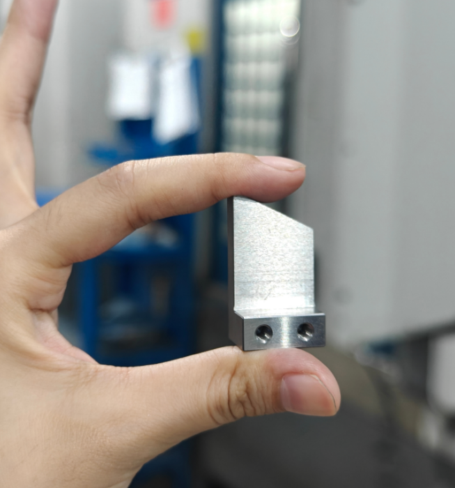
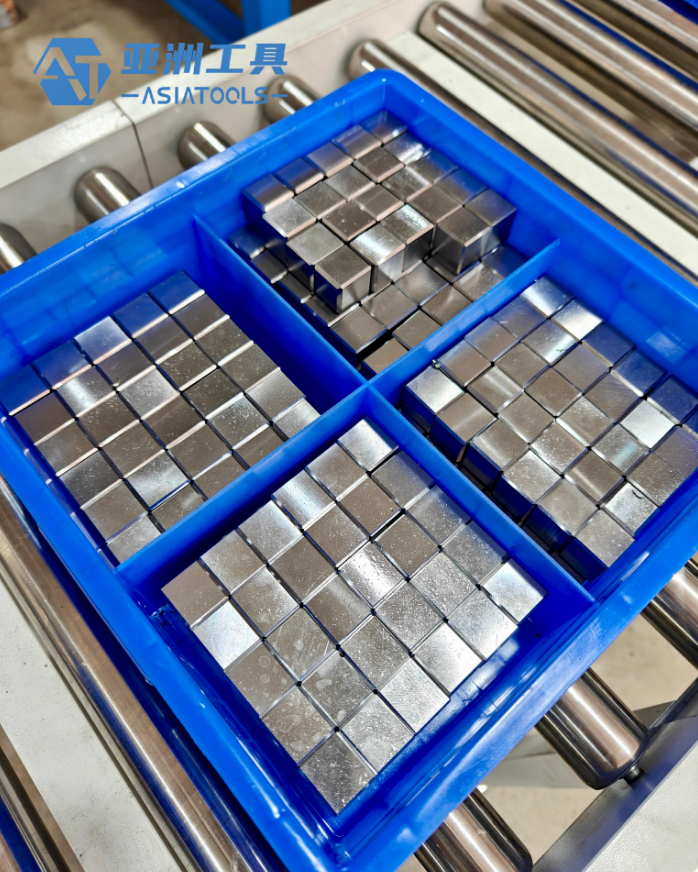
Inserts
Pre-Hardened Hardness
At the steel mill, multi-ton P20 blocks are heated thoroughly in a controlled furnace at 860°C, rapidly quenched in oil, then tempered for dozens of hours at 550–600°C. After this energy-intensive heat treatment, the steel arrives at the mold shop already at 28–32 HRC.
Untreated mild steel is typically only around 150 HB. When 200°C molten plastic is injected into the cavity at 1000 bar, its surface cannot hold pressure and quickly dents. The as-supplied hardness of P20 withstands repeated high-pressure injection of PC or ABS for thousands upon thousands of cycles.
When machinists receive the steel plate, they clamp it to the CNC table, machine it to final external dimensions, and put it straight into service. Years ago, when soft steel was used, parts had to be sent out for heat treatment after machining, adding a full three days to lead time.
If a precision soft-steel insert measuring 50 mm by 50 mm goes through furnace treatment, its volume can change uncontrollably by 0.1% to 0.3% through expansion and contraction. The tolerance on insert fit in the mold base is often held to ±0.005 mm. If the insert grows by 0.05 mm, it simply will not fit into the reserved pocket. Hammering it in would damage the contact surfaces. Pre-hardened steel removes the risk of dimensional scrap caused by thermal distortion.
When the factory buys thick P20 plates over 300 mm thick, slight hardness differences may still exist between the surface and the center:
· Surface hardness can reach 31 HRC
· Hardness at the center may be 29 HRC
· Hardness variation at different depths is kept within 2 HRC
· Even when several centimeters are machined away to form a complex insert, the bottom still retains full compressive strength
Machining pre-hardened steel throws sparks, and temperatures around the tool tip can reach 300°C. Operators switch to TiAlN-coated carbide cutters, set spindle speed to 6000–8000 rpm, and keep the depth of cut between 0.15 and 0.3 mm.
The fine chips come off dark blue, carrying away 80% of the heat from the cutting zone. The operator mixes emulsion oil into the machine tank at a ratio of 1:20 and increases coolant pressure to flush chips away. With continuous coolant directed at the tool, the cutting edge wears down at about 0.02 mm per hour. Every four hours, the machinist checks remaining tool length with a micrometer and manually updates tool compensation in the machine system.
When the work calls for an ultra-fine 0.8 mm ejector pin hole, a carbide milling cutter cannot fit. The operator then switches to slow wire cutting:
· A 0.2 mm brass wire is threaded and energized with high voltage
· Sparks in the water tank melt through the hardened steel
· Cutting parameters are set to remove 60–80 mm² of metal per minute
· The measured verticality error of the deep hole is less than 0.005 mm
The inspector scans the part with a CMM ruby probe, and all profile error stays within the drawing requirement of ±0.01 mm. Then the polishing technician uses wool felt loaded with 2000-grit diamond powder over the HRC 30 surface. Because the hardened steel resists orange peel and texture defects, the surface roughness can be brought down to 0.05 μm in half an hour, producing a mirror-like reflection.
When a 50 mm-thick insert needs internal cooling passages, the operator uses a horizontal deep-hole drilling machine. A 6 mm carbide gun drill is pressed against the side of the insert. Under 100 bar high-pressure oil lubrication, the drill advances 15 mm per minute, creating a straight cooling channel through the hardened metal.
The design fit clearance is 0.005–0.014 mm. The insert slides slowly into place under gravity, and the seams around it become nearly invisible. Once installed, the mold is mounted on a 250-ton injection press, opening and closing three times per minute, and can run for 300,000 shots without producing flash.
If the factory is molding PA66 engineering plastic with 20% glass fiber, cavity wear becomes severe. The hardened insert edges can hold for three months without chipping, and the flash thickness on the molded parts remains below 0.02 mm, allowing the parts to pass full inspection smoothly.
After the machine completes its 300,000-shot production target, the mold is disassembled and the metal insert enters the maintenance process:
· Soak it in a strong alkaline solvent heated to 60°C to remove black gas residue
· Use a portable Rockwell hardness tester to measure hardness loss at three points on the working surface
· Measure wear-prone thin-wall sections with a micrometer to check dimensional change
If the caliper shows edge wear greater than the 0.03 mm scrap threshold, the worker disconnects the cooling hose, removes the M8 retaining screw at the bottom, takes out the worn insert, and replaces it with a newly machined spare from inventory. The heater bands around the injection barrel are powered up again, the temperature rises back to 240°C, and production resumes.
Cutting Parameters
The machinist places a 15 kg pre-hardened steel block onto the machining center table and tightens the vise flange nuts with both hands. The tool magazine is filled with more than a dozen cutters of different sizes, all ready for machining HRC 30 steel. The control screen lights up, and the operator starts entering the speed and feed values that determine how aggressively each tool will work.
The spindle arm picks up a 50 mm face mill fitted with five TiAlN-coated carbide inserts. The operator enters 800 rpm for spindle speed and 1200 mm/min for feed speed. The face mill starts removing metal at a rate of about 80 cm³ per minute.
Each pass cuts 1.5 mm deep, and the width of cut is 60% of the cutter diameter, sweeping across a 30 mm-wide section in one stroke. At the moment the tool hits the hardened steel, the tool tip temperature surges to 400°C. Chips turn dark blue from the heat and strike the protective enclosure with a crisp metallic sound.
At this stage, the coolant pipes remain shut off. If cold cutting fluid hits a 400°C carbide insert directly, the sudden thermal shock can create dozens of microscopic cracks in the edge within just three minutes. Instead, the operator uses compressed air at 8 bar to blast the tool head and carry away the hot chips.
After the face mill has been running hard for 45 minutes, inspection shows flank wear close to the 0.2 mm discard limit. The spindle returns to its home position, the tool changer removes the face mill, and a 12 mm four-flute end mill is loaded. By now, less than 0.5 mm of stock remains to be removed according to the drawing.
| Operation | Tool Specification | Spindle Speed (rpm) | Feed Rate (mm/min) | Depth per Pass (mm) | Cooling Method |
| Heavy stock removal | 50 mm face mill | 800 | 1200 | 1.50 | 8 bar air blast |
| Local surface finishing | 12 mm carbide end mill | 4500 | 1800 | 0.20 | 1:20 emulsion |
| Fine-detail finishing | 4 mm ball-end mill | 12000 | 2500 | 0.05 | Vegetable-based oil mist |
The new 12 mm end mill takes over. Spindle speed rises to 4500 rpm. This tool removes the rough steps left behind by the previous operation, while the depth of cut is reduced to 0.2 mm. Feed rate increases to 1800 mm/min.
The low, heavy cutting sound becomes a sharp whistle. The coolant pump starts, sending the white emulsion mixed at 1:20 through the center hole of the tool holder and onto the cutter. The lubricating fluid keeps the cutting edge temperature below 100°C.
Each pass over the HRC 30 surface removes a 0.05 mm layer of metal. When the workpiece contains an internal R2 mm corner, the 12 mm flat-end mill is too large to enter. The spindle stops, and the tool arm changes to a 4 mm ball-end cutter.
Now the tool tip has to behave like a brush, sculpting a smooth curved surface in steel, with only 0.1 mm of stock left according to the drawing. Because the shank of the 4 mm ball-end tool is very slender, it cannot تحمل excessive cutting force; too much load would snap it at the base. The operator sets spindle speed all the way up to 12000 rpm.
Feed rate rises to 2500 mm/min. An external minimum-quantity lubrication system sprays 50 ml of vegetable-based cooling oil mist per hour into the cutting zone. The ball-end mill sweeps back and forth in a zigzag path over the steel surface, with a step-over of only 0.05 mm each pass.
The chips are so fine they look like powder, and when mixed with the oil mist they become black slurry. This program runs for a full three hours inside the machine, one pass after another, bringing the surface finish down to Ra 0.8 μm. After three hours of continuous cutting on hardened steel, the radius wear on the tip of the coated imported tool reaches 0.015 mm.
The finished dimensions cannot tolerate an error of even a few microns. A Heidenhain tool setter rises from the corner of the machine, and while the tool is spinning, it interrupts the red laser beam to measure the actual cutter diameter. The laser detects 0.012 mm of tool wear and sends the value back to the Siemens 840D CNC controller.
The next tool compensation value is reduced by that amount, so the spindle cuts 0.012 mm deeper on the next pass. After the part is removed and sent for blind inspection in the CMM room, all 50 hole positions are found to fall within the drawing requirement of ±0.005 mm. On the reverse side, the workpiece also includes M6 threaded blind holes.
A standard twist drill tends to skate and wander on an HRC 30 surface. The machine switches to a 135-degree cobalt internal-coolant drill. At 1500 rpm and with 20 bar coolant pressure, the drill is forced straight into the metal. A 15 mm-deep blind hole is completed in under four seconds.
Once the blind hole is drilled, the spindle changes to a form tap for the M6 internal thread. Instead of cutting chips, the tap uses the spindle’s torque to cold-form the thread profile in the wall of the metal. It advances at a low forward speed of 400 rpm.
The moment it reaches the drawing depth of 12 mm, the spindle reverses and withdraws. The formed thread has about 30% higher tensile strength than a cut thread. On the injection press, where the part endures thousands of opening and closing vibrations every day, the formed thread grips the M6 fastener tightly and prevents screw loosening or water leakage for at least half a year.
Impact Resistance
After polishing the P20 steel block to a mirror finish of Ra 0.05 μm, the technician fits it into a large mold base and locks it in place with copper rod taps around the edges. The shop crane lowers its hook, lifts the 5-ton assembly, and slowly installs it into a large injection molding machine rated at 500 tons of clamping force. Workers connect the 380 V industrial power supply, and the heater bands around the barrel bring transparent polycarbonate (PC) pellets up to 280°C.
The PC melts into a viscous, transparent liquid in the heated barrel. At the back of the machine, the servo motor drives a heavy 60 mm-diameter screw that rotates furiously, pushing the melt toward the front of the barrel.
The screw then acts like the plunger of a giant syringe, forcing the accumulated melt through a gate only 3 mm in diameter. Under a massive hydraulic pressure of 1200 bar, the molten plastic turns into a high-speed jet traveling at 300 mm/s, slamming directly into the thinnest and weakest projection on the insert.
Ordinary soft steel would visibly bend by 0.02 mm in a thin 0.5 mm wall under such flow force, turning the whole part into scrap.
Pre-hardened P20 steel typically delivers around 1000 MPa in tensile strength and a yield strength of about 800 MPa.
Thanks to its as-supplied hardness, the tightly bonded iron atoms inside the metal withstand the direct impact of that plastic surge. Once the cavity is filled, the injection machine immediately shifts into holding pressure, maintaining 800 bar to continue packing plastic into the cavity and prevent sink caused by cooling shrinkage.
After the 5-second hold pressure countdown ends, the plastic temperature inside the mold drops sharply from 280°C to 120°C. Cooling channels embedded inside carry 15°C well water, pulling heat rapidly out of the steel. As the plastic shell cools, it contracts and grips the metal core tightly like a tensioned steel cable.
The hydraulic cylinder then pulls the moving platen back at 500 mm/s. The ejector plate inside the mold base pushes forward and forcibly strips the molded plastic shell off the metal core. This aggressive mechanical release creates severe sliding friction on the metal contact surfaces.
A full molding cycle takes 25 seconds. The production schedule in the workshop specifies round-the-clock operation, meaning this metal insert weighing less than 1 kg is hit by high-temperature, high-pressure plastic flow 3,450 times per day.
After a month of continuous operation and 100,000 shots, every mold closing event has been a metal-on-metal impact between steel plates weighing several tons. The material composition lists 0.30%–0.55% molybdenum, and those molybdenum atoms strengthen the lattice and extend fatigue life. Even after 100,000 violent impacts, no fatigue cracks can be found in the gate area that bears the greatest load.
If the PC is replaced with PA66 containing 30% chopped glass fiber, conditions become even harsher. Barrel temperature rises to 300°C. Hard glass fibers mixed into the molten resin become millions of microscopic files under pressure.
These fast-moving glass particles constantly scrape across the metal surface thousands of times a day.
Tests using cheaper 45 carbon steel show that after just 10,000 shots, 0.05 mm of surface material is worn away, and the molded parts develop burr-like flash around the edges. But with 1.40%–2.00% chromium in the steel, this abrasive cutting action is resisted effectively.
Chromium and carbon combine into hard chromium carbide particles distributed throughout the metal. After months of glass-fiber abrasion, the surface loses only 0.01 mm in thickness. The factory inspector checks the outer diameter of parts from the 150,000th shot with calipers and finds every reading still within the drawing tolerance of ±0.05 mm.
To shorten cooling time, the mold designer drills a conformal cooling channel just 5 mm below the metal surface. Cold water at 15°C flows through it at 20 liters per minute, while the outside of the metal is exposed to 280°C molten resin. This creates huge thermal expansion and contraction forces across only a few millimeters of steel section.
Ordinary iron would quickly develop spiderweb-like surface cracks under such repeated temperature swings. With a thermal conductivity of 30 W/(m·K), heat is pulled rapidly away from the surface toward the water channels. Because heat does not build up at the skin, the risk of thermal cracking is greatly reduced.
By the time the machine reaches 300,000 shots, the operator removes the insert and examines the hardest-hit R1.5 mm corner under 10× magnification.
· No fine network-like heat cracks can be found on the surface
· The mirror-polished Ra 0.05 μm area shows only slight dark oxidation
· A thickness gauge shows just 0.015 mm of material loss at the corner
· Even under 1200 bar pressure, the cooling channel walls show no corrosion pits or leakage points
When the metal blade section is as thin as 0.8 mm, the vibration generated as the two heavy mold plates close can easily snap it. The moving and fixed platens collide at 50 mm/s, and the impact from several tons of steel bears directly onto this thin metal section.
To prevent that, the mold technician machines four precision locking blocks with a 7-degree taper around the mold base. Just before impact, the locking blocks engage physically and hold the two large steel plates within 0.01 mm of movement, effectively cutting off the lateral tearing force that would otherwise damage the metal.
· The closing impact from several tons is redirected through the reinforced guide pillars of the mold base
· The thin-wall metal section avoids fracture caused by lateral vibration
· The steel’s 1000 MPa tensile strength withstands the remaining longitudinal compressive force
After running at full load for an entire year, the machine counter shows 1 million qualified plastic housings produced. Workers can still find early soft-steel test pieces in the scrap bin—those parts broke in two after fewer than 2,000 shots, with jagged fracture surfaces that looked torn apart.
Good steel survives daily exposure to high-pressure flow impact, shrinkage pull from cooling plastic, and ejector friction during mold opening. The injection machine also avoids dozens of hours of downtime that would otherwise be needed to remove the mold and remachine a replacement insert. At the morning shift change, the shop supervisor opens the machine logbook and keeps production moving.

General Tooling
No Additional Heat Treatment Required
A 5-ton overhead crane places a P20 steel plate measuring 1.2 meters long and 0.8 meters wide onto the CNC machine table. Workers tighten the M24 fixing bolts, and the spindle begins cutting at 3500 rpm. The 3-ton steel block enters machining the very same day it arrives at the factory.
Before the material enters storage, the inspector scans the plate surface with an ultrasonic flaw detector. The 2.5 MHz reflection trace appears as a straight line on the screen. After scanning 2 square meters of area and finding no internal voids larger than 2 mm, the workshop supervisor signs off and the forklift sends the material to the machining zone.
If the material were untreated S136 instead, it would be much softer when delivered, with hardness around 15–20 HRC. After machining, it would need to go into a vacuum furnace at 1020°C, then through annealing at 500°C with a 4-hour hold. That process alone adds 7–10 days of waiting time.
Outsourced furnace heat treatment is charged by weight, adding RMB 3–5 per kilogram. For a 3-ton steel block, the heat-treatment bill alone exceeds RMB 15,000. Once the steel is heated red-hot and quenched in water, the rapid cooling leaves it full of stress and vulnerable to cracking.
A 600 mm-square steel block can distort by 0.1–0.3 mm after quenching at 850°C. But the dimensional red line for an injection mold base is 0.02 mm. If the block ends up off by 0.3 mm, it is effectively scrap. To hedge against distortion, shops are forced to leave an extra 0.5 mm of stock before heat treatment and then grind it down slowly afterward.
Large steel mills solve these downstream machining problems in advance with heavy-duty equipment:
· Supplied hardness is held firmly within 28–32 HRC
· Even in a 500 mm-thick plate, inside-to-outside hardness difference is under ±1 HRC
· Post-hardening grinding costs are removed, while dimensions can be held to 0.01 mm
· Delivery time for medium and large mold bases is cut from 45 days to within 25 days
Industrial furnaces stretching hundreds of meters run day and night, processing steel billets over ten meters long. The temperature rises at a controlled rate of 50°C per hour until it reaches 860°C, followed by several hours of soaking. The billets are then moved into massive oil tanks for cooling.
Afterward, they are transferred to tempering furnaces and held at 550°C for more than ten hours. Such ultra-large temperature-control furnace systems cost tens of millions. By buying pre-hardened P20, an ordinary machine shop effectively benefits from the temperature-control capability of a major steel mill’s enormous capital equipment at a very low unit cost.
On a 15 kW machine, a 63 mm face mill is mounted. The tool cuts 2 mm deep into the steel and advances at 800 mm/min. The spindle load meter stays steady at a safe 45%. With high-pressure coolant flushing the cut, the machine can run for 24 hours straight and remove over 300 kg of waste metal.
At the finishing stage, the shop switches to an 8 mm cutter and reduces depth of cut to 0.1 mm. Spindle speed rises to 8000 rpm as it machines complex 3D surfaces into the metal. Because the material comes with its hardness already in place, there are no localized hard spots, and cutting resistance remains stable throughout.
A bench technician spends two hours polishing with imported 400-grit abrasive paper until the surface reaches Ra 0.8 μm. By avoiding the heat-treatment step altogether, the savings to the workshop are easy to see:
· Eliminate 2–3 days of transport time to and from an off-site heat-treatment plant
· Completely avoid the risk of 100% material loss from quench cracking in a single mold
· Reduce grinding wheel consumption by 40% when grinding hardened steel
· Cut bench fitting time for large molds from 50 hours to 15 hours
General Tooling Applications
A Haitian injection molding machine rated at 1500 tons is running in the workshop. On the platen sits a large block of steel measuring 1200 mm by 900 mm—a 2.5-ton P20 mold base. Four steel guide pillars, each 60 mm in diameter, slide into brass bushings.
The clearance between pillar and bushing is held within 0.02 mm. Every 45 seconds, the machine injects plastic heated to 280°C into the mold at 120 MPa. This heavy steel plate withstands 800 tons of machine force without any deformation in the housing.
If that 400 mm-thick base plate were made from cheap A3 mild steel instead, it would begin sinking by 0.15 mm in the middle after fewer than 10,000 cycles. The current P20 base plate has already been through 500,000 opening and closing cycles, and measurement still shows less than 0.03 mm of surface height variation.
The CNC operator also has to drill 25 mm cooling channels deep into this 1.2-meter-long block. A 1.5-meter-long drill turns at 800 rpm and feeds into the metal at 40 mm/min, while chips continue to stream out through the flutes.
In the next workshop, aluminum housings are being machined. To hold the aluminum block in place, the setup relies on an 18 kg pneumatic clamp. Guided by two 12 mm locating pins, the worker places the part accurately into the fixture pocket.
With an 8 kg pressure airline connected, the iron clamp locks the part instantly, applying a downward force of 300 kg. As the cutter spins at 12,000 rpm to machine the aluminum, the intense vibration is absorbed by the steel plate beneath.
Alkaline coolant mixed with aluminum chips splashes over the clamp more than 500 times in a single shift. If the fixture were made from ordinary 45 steel, it would be covered in rust pits in half a month. But the 1.5% chromium content in P20 allows it to sit in water for 60 days with very little corrosion.
After 80,000 loading and unloading cycles, the inspector measures the two 12 mm locating pins. The dial shows only minimal wear—just 0.005 mm. The machine’s programmed zero point remains stable and unchanged.
Every month, the purchasing officer reviews the accounts to calculate how many tooling components were scrapped across the plant’s machines. Next quarter’s budget for metal spare parts has to be kept within RMB 200,000.
| Equipment / Tooling | Working Load | Allowable Dimensional Change | Expected Service Life |
| 500-ton injection mold base | 120 MPa hydraulic pressure | ±0.02 mm | 250,000 clamping cycles |
| Pneumatic fixture block | 300 kg downward force | ±0.005 mm | 80,000 part loading cycles |
| Press brake V-die block | 100 tons pressing force | Edge wear under 0.1 mm | 150,000 sheet forming cycles |
| Conveyor base support plate | 2-ton static load | Flatness variation 0.05 mm | 40,000 continuous operating hours |
In the stamping area, a press brake delivering 100 tons of force is bending 2 mm sheet metal. The upper punch drives the flat sheet down into the V-shaped lower die, forming a clean 90-degree angle.
The milling operator cuts the V-groove to exactly 16 mm wide and machines a 0.5 mm radius at the bottom. The machine cycles 15 times per minute, and every hit concentrates 80 tons of force onto a 200 mm-long steel block.
When producing a batch of 3-meter elevator door panels, the machine may strike 4,000 times without stopping. The zinc-coated sheet repeatedly rubs against the lower die, driving localized temperatures up to 180°C. Yet the steel does not pit or pick up flaked zinc.
Even after 150,000 cycles, inspection shows the groove edges have worn by less than 0.1 mm. Spending RMB 18,000 on a hard and costly D2 tool steel set is not cost-effective. A P20 steel block cut for about RMB 4,500 is more than sufficient for bending mild sheet steel.
The heavy shaft beneath the conveyor belt is machined from 80 mm solid round steel. A 5 kW motor drives it continuously, subjecting the shaft to 150 N·m of torque every second. It rotates steadily at 60 rpm day after day.
At the bearing seats on both ends, the machine grinds away 0.05 mm of stock, leaving only +0.002 to +0.015 mm of fit allowance. If the belt occasionally jams and kicks back, the steel’s own toughness absorbs the shock. Harder but more brittle steels are far more likely to snap in two under that kind of vibration.
When the plant electrician replaces a worn plastic pulley on the belt, he removes four M10 bolts with a wrench. Those threaded holes in the base had previously been tightened to 45 N·m, yet the threads still show no sign of flattening or stripping.