

Mold steel does not need grinding just because it has been milled. If the part already meets the required flatness, parallelism, thickness, and surface finish after it is unclamped and inspected, there is little reason to grind it again.
Grinding becomes useful when those final requirements are difficult to hold by milling alone, or when heat treatment has moved the part. This is especially common with precision flat faces, hardened inserts, large plates, and parts where two opposite surfaces must stay closely parallel.
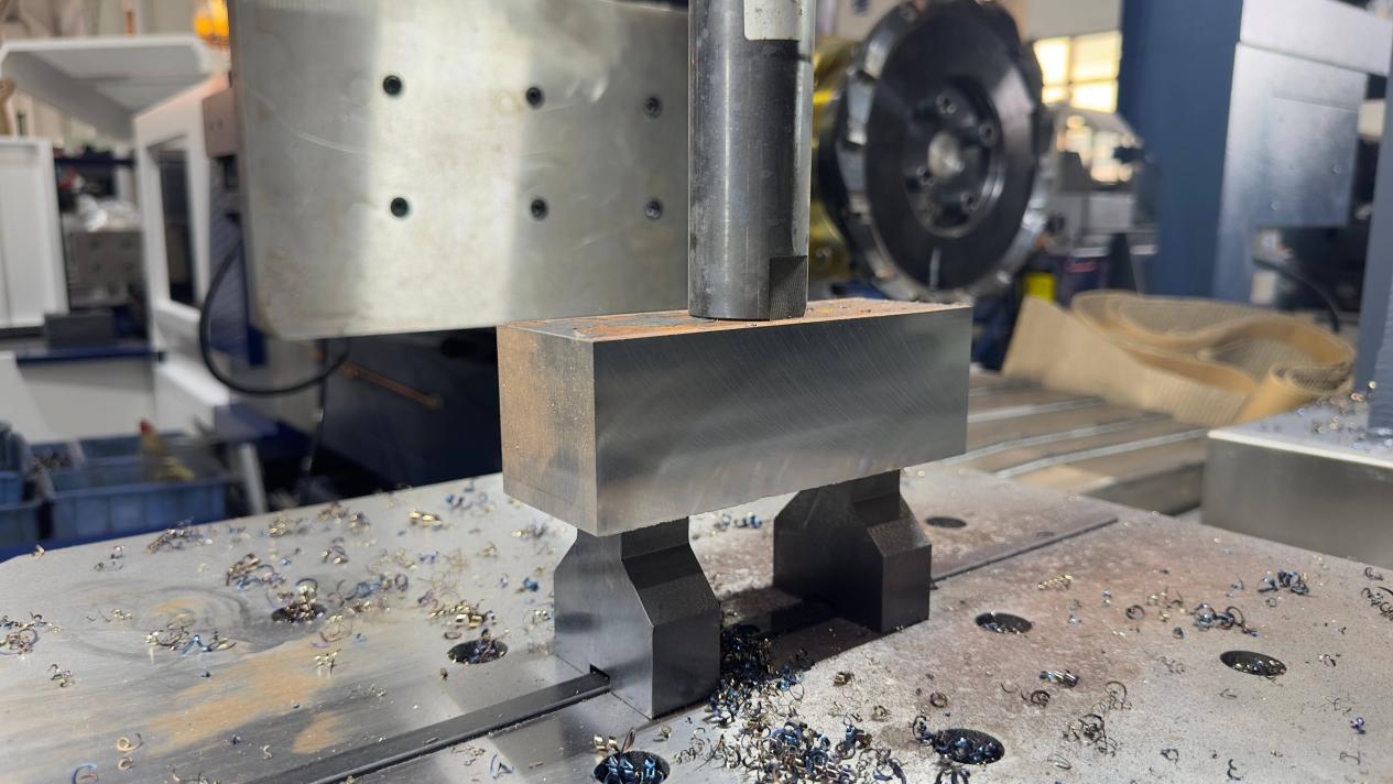
A useful way to think about it is simple: milling creates most of the shape; grinding is often the last small correction. Sometimes that correction is only 0.05 or 0.10 mm, but that small amount can decide whether the part passes a 0.01 mm flatness or thickness requirement.
Quick Guide
| Condition | Milling | When Grinding Makes Sense |
|---|---|---|
| General mold plate | Usually enough for moderate tolerances | Critical datum, thickness, or mating faces |
| Pre-hardened P20-type steel | Common finishing method | Tight flatness, parallelism, or thickness |
| Flatness above 0.03-0.05 mm | Often achievable | Mainly depends on plate size and rigidity |
| Flatness around 0.01-0.02 mm | Possible on small rigid parts | More useful as the part becomes larger or less stable |
| Flatness below 0.01 mm | Possible with very good process control | Commonly handled by grinding on simple flat faces |
| Final thickness ±0.02 mm | Often possible | Useful on larger or less stable parts |
| Final thickness ±0.01 mm | Possible | Often safer on precision flat parts |
| Final thickness ±0.005 mm | Possible only under controlled conditions | Precision grinding becomes much more attractive |
| Hardened insert | Hard milling works well for complex surfaces | Useful for flat datum and reference faces |
| Heat-treated plate | Inspect first | Used when measured distortion needs correction |
| Large thin plate | Higher deformation risk | Can help, but workholding and stress control matter |
| Ra 1.6 µm | Normally achievable | Usually unnecessary for roughness alone |
| Ra 0.8 µm | Normally achievable with good finish milling | Useful when geometry also needs correction |
| Ra 0.4 µm | Possible with controlled finishing | Useful when fine finish and tight geometry are both required |
The numbers above are useful for planning, but they are not hard process limits. A 50 × 50 mm insert with 0.01 mm flatness is one thing. An 800 × 500 mm plate with the same 0.01 mm requirement is a very different job.
Flatness
Flatness is probably the most common reason mold steel ends up on a grinder after milling.
Take a plate measuring:
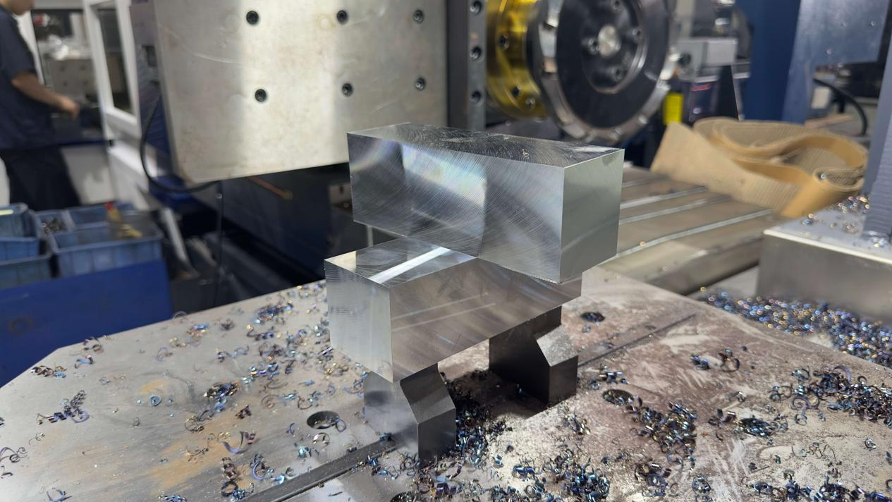
400 × 300 × 40 mm
with a drawing requirement of:
Flatness: 0.01 mm
That means the whole controlled surface has to fit inside a flatness zone only 0.01 mm wide. It does not mean the thickness simply has to measure 40.00 mm at a few points. A plate can have nearly identical thickness readings at the corners and still be bowed through the middle.
ISO 1101 defines the international rules used for geometrical tolerancing, including flatness and orientation requirements.[1]
Flatness errors usually come from a mixture of things rather than one obvious cause. Cutter runout, tool deflection, uneven material removal, clamping, residual stress, heat, and poor support can all contribute.
Clamping
Clamping is easy to underestimate.
Imagine a slightly bowed plate on a machining table. Tighten the clamps and the plate is forced down. Machine the top face, check it while it is still restrained, and everything may look fine.
Then remove the clamps.
The plate moves back.
Depending on the material and geometry, that movement might be 0.02 mm, 0.05 mm, or more. The CNC did not necessarily cut badly. The part simply changed shape after the force holding it flat disappeared.
Grinding can have the same problem. A magnetic chuck may pull a thin plate flat while the wheel is working. Once the magnet is released, the plate may spring again.
So grinding only fixes flatness when the part itself is stable enough to keep that shape.
For thin or stress-sensitive parts, shops often rely on lighter cuts, balanced stock removal from both sides, lower holding force, several machining stages, and inspection after the part is released. Stress relief may also be used when the material and process call for it.
Workholding becomes especially important on large mold blocks. This guide on hydraulic clamping pressure and mold steel deformation goes deeper into that part of the process.
Temperature
Once tolerances get small, temperature starts showing up in the measurement whether you want it to or not.
A useful approximate thermal expansion range for many common steels is:
10-12 µm/m/°C
Take a 500 mm steel part that is 5°C warmer than the reference condition:
500 mm × 5°C × 10-12 µm/m/°C ≈ 0.025-0.030 mm
That is already larger than a ±0.01 mm tolerance.
Even a 1,000 mm plate with only a 2°C temperature difference can change by roughly:
0.020-0.024 mm
ISO 1 specifies 20°C as the standard reference temperature for dimensional and geometrical properties.[2] NIST also documents 20°C as the established reference temperature used in industrial dimensional measurement.[3]
This does not mean every mold shop needs a metrology laboratory. It does mean that measuring a hot plate straight off the machine and comparing it with a micron-level tolerance can give the wrong picture.
Parallelism
Flat does not automatically mean parallel.
Suppose an insert measures:
Left side:
30.000 mm
Right side:
30.025 mm
The difference is 0.025 mm. Both surfaces could be individually flat and the part would still have a wedge shape.
That wedge can change insert height, contact with the backing plate, shut height, load distribution, and alignment.
This is where surface grinding is very useful. One face is first established as the reference. The opposite face is then ground relative to it. In one operation sequence, the shop can control flatness, parallelism, and final thickness together.
For earlier blank preparation, a CNC duplex milling machine can machine opposite faces with fewer reclamping operations. Grinding only needs to follow if the final geometry still demands it.
Thickness
Thickness tolerance looks simple on a drawing, but the allowed window can become very small very quickly.
| Drawing Size | Allowed Range | Total Tolerance Band |
|---|---|---|
| 25.00 ±0.05 mm | 24.95-25.05 mm | 0.10 mm |
| 25.00 ±0.02 mm | 24.98-25.02 mm | 0.04 mm |
| 25.00 ±0.01 mm | 24.99-25.01 mm | 0.02 mm |
| 25.000 ±0.005 mm | 24.995-25.005 mm | 0.010 mm |
At ±0.005 mm, the total legal size range is only 0.010 mm.
That 0.010 mm has to absorb all normal process variation: tool wear, runout, thermal growth, workpiece temperature, clamping movement, material movement, and measurement uncertainty.
This is why machine accuracy and part accuracy are not the same thing.
A CNC machine may have a published positioning accuracy of 0.005 mm. That does not mean every part coming off the table can automatically be guaranteed to ±0.005 mm.
For simple flat parts, grinding becomes more attractive as the requirement moves from ±0.02 mm toward ±0.01 mm and ±0.005 mm, especially when the part is large, hardened, or prone to movement.
Surface Finish
Surface finish is another reason people specify grinding, but it is also where a lot of confusion starts.
Typical Ra values on mold and tooling drawings include:
- Ra 3.2 µm;
- Ra 1.6 µm;
- Ra 0.8 µm;
- Ra 0.4 µm;
- Ra 0.2 µm.
Ra 1.6 µm and Ra 0.8 µm are commonly within finish-milling capability on suitable mold steel. Ra 0.4 µm is also possible with a good machine, a healthy spindle, correct inserts, and stable cutting conditions.
Ra 0.2 µm is more demanding. Depending on the surface and function, fine grinding, lapping, polishing, or a very well-controlled high-speed machining process may make more sense.
But there is a more important point: Ra does not tell you whether the surface is flat.
| Part | Surface Roughness | Flatness |
|---|---|---|
| Plate A | Ra 0.3 µm | 0.080 mm |
| Plate B | Ra 0.8 µm | 0.008 mm |
Plate A is smoother. Plate B is ten times better in flatness.
If this is an insert seat or datum face, Plate B may be the better part even though its Ra number is higher.
Also, Ra 0.4 µm is numerically half of Ra 0.8 µm. That does not mean the surface is twice as accurate.
ISO 21920-2 defines profile surface-texture terms and parameters.[4] NIST surface-metrology work separately treats parameters including Ra, Rq, Rz, Rt, Rp, Rv, and spacing characteristics.[5]
For a normal reader, the useful distinction is this:
- Ra tells you about average roughness;
- Rz gives more information about larger peak-to-valley variation;
- lay tells you the main direction of the machining marks;
- waviness describes broader surface variation that Ra may not show clearly.
If you need to check milled surfaces before deciding whether rework is necessary, see how to inspect surface roughness after duplex milling.
Heat Treatment
Heat treatment is one of the clearest reasons to leave stock for final correction.
A part can be perfectly acceptable before hardening and change afterward.
The movement may show up as a change in length, width, thickness, flatness, straightness, squareness, or the relationship between datum faces.
Heat-treatment distortion can come from thermal stress, residual-stress release, and phase transformation. U.S. Department of Energy technical material on steel heat treatment discusses these same sources of dimensional and shape change.[6]
It helps to separate two kinds of movement.
Dimensional change:
100.00 mm → 100.05 mm
The part has simply become 0.05 mm larger in that dimension.
Shape distortion:
The part may bow, twist, taper, or move differently in different areas.
The second case is usually harder to fix. A part can show very little average size change and still have enough bow to fail a 0.01 mm flatness requirement.
Vacuum hardening does not mean zero distortion either. It gives good control over atmosphere and process conditions, but it does not eliminate machining stress, thermal gradients, phase change, or quenching effects.
The difference between pre-hardened material and steel that will be hardened later is covered in more detail in how heat treatment affects mold steel machining performance.
Machining Sequence
A typical route for a precision hardened insert might look like this:
Saw → Rough Mill → Stress Relief if Needed → Semi-Finish → Harden and Temper → Inspect → Grind or Hard Mill → Final Inspection
The important part is the timing. Do not finish critical faces too early if a later operation is likely to move them.
Rough milling removes most of the stock. If possible, avoid removing a huge amount of material from only one side while leaving the opposite side untouched.
Stress relief may be useful for large, asymmetric, deeply pocketed, or tightly toleranced parts. It is not something every mold block automatically needs.
Semi-finishing brings the part close to final geometry but leaves enough material for later correction.
After hardening, measure the part before deciding what to grind.
The useful sequence is:
heat treat → inspect → find the high and low areas → choose the final finishing process.
That may mean grinding one face, grinding both faces, hard milling a cavity, straightening first, or in some cases stopping because too little material remains to recover the part.
Grinding Allowance
Grinding allowance is one of those areas where a simple number can be misleading.
There is no universal allowance that works for every mold steel part.
As practical shop-planning examples:
- small, stable precision faces may use about 0.05-0.15 mm per surface;
- larger or more distortion-prone hardened parts may use about 0.15-0.30 mm per surface or more.
These are working ranges, not standards.
The actual amount depends on the steel, part length, thickness, heat treatment, previous stress relief, expected bow or twist, and final tolerance.
Also be very clear about one thing: per face and total stock are not the same.
| Allowance per Face | Total on Two Opposite Faces |
|---|---|
| 0.05 mm | 0.10 mm |
| 0.10 mm | 0.20 mm |
| 0.15 mm | 0.30 mm |
| 0.20 mm | 0.40 mm |
A useful way to plan it is:
finishing stock = expected distortion + cleanup + final size correction + process margin
Not a formal formula, just a practical way to avoid leaving too little material.
Grinding Allowance Example
Suppose the finished insert thickness is:
50.000 ±0.010 mm
The total tolerance band is:
0.020 mm
Before hardening, the part measures:
50.30 mm
Total finishing stock:
0.30 mm
If it is split evenly:
0.15 mm per face
That sounds like a lot compared with a 0.020 mm final tolerance band. But not all 0.30 mm is available just for size adjustment.
If heat treatment leaves a high area that needs 0.18 mm of cleanup before the face becomes fully flat, much of the allowance is already gone.
This is why a warped part cannot be judged from average thickness alone.
Part Size and Rigidity
A tolerance gets harder as the surface gets larger.
| Part | Size | Flatness |
|---|---|---|
| Small insert | 50 × 50 × 20 mm | 0.01 mm |
| Large plate | 800 × 500 × 40 mm | 0.01 mm |
Same tolerance, very different job.
The larger plate is affected more by temperature, support position, machine travel, residual stress, its own weight, and clamping.
Thickness matters just as much.
Compare:
500 × 300 × 12 mm
with:
500 × 300 × 80 mm
The 12 mm plate is less than one-sixth as thick. It will react much more strongly to clamps, cutting forces, heat, and internal stress.
For large blanks that need clean reference faces before precision work, six-side milling of mold steel blocks can help establish those surfaces. When opposite faces need to be machined efficiently, double-sided milling can reduce repeated setups.
Steel Hardness
Hardness changes both cutting and grinding behavior, but hardness alone does not decide whether a part needs grinding.
| Steel Type | Typical Condition | Common Finishing Approach |
|---|---|---|
| P20 / 1.2311 type | About 28-36 HRC when supplied pre-hardened | Finish milling is common; grind critical flats if needed |
| 1.2738 type | About 33-38 HRC in common pre-hardened supply | Milling is common; grinding used for tighter reference geometry |
| H13 / 1.2344 type | Often about 45-52 HRC in working condition | Hard milling for complex geometry; grinding for precision flats |
| D2 / 1.2379 type | Often high-50s to low-60s HRC after hardening | Grinding wheel choice and heat control become more important |
These are common working ranges, not fixed requirements.
P20 / 1.2311 mold steel is often machined in its supplied pre-hardened condition, so many parts never go through a final quench-hardening cycle.
1.2738-type mold steel is also commonly used in a pre-hardened condition for larger mold components.
H13 / 1.2344-type steel is commonly hardened for tooling service. Its cavities may be hard milled while datum or support faces are ground.
D2 / 1.2379-type steel contains a high amount of hard carbides. Two steels at the same HRC can therefore behave differently on a grinder.
Hard Milling or Grinding?
These two processes are not fighting for the same job every time.
| Feature | Usually Better Suited Process |
|---|---|
| Flat datum face | Grinding |
| Two closely parallel faces | Grinding |
| Final precision thickness | Grinding |
| Complex 3D cavity | Hard milling |
| Freeform mold surface | Hard milling |
| Narrow internal feature | Hard milling, EDM, or jig grinding depending on geometry |
| Precision round outside diameter | Cylindrical grinding |
A hardened H13 insert at around 50 HRC may have its cavity hard milled while only the bottom datum and one or two reference faces are ground.
For large accessible flats, a CNC surface grinding machine is a natural choice. It is not the right machine for every cavity or internal feature.
Datum and Insert Seats
Datum faces deserve more attention than their appearance suggests.
Suppose a mold insert requires:
- Face A flatness: 0.01 mm;
- Face B parallelism to A: 0.01 mm;
- overall thickness: 40.00 ±0.01 mm.
Face A should normally be established first. Face B can then be finished from that reference while the shop controls parallelism and thickness.
Insert seats have a similar problem.
On a 100 × 80 mm seat, a local high spot of only:
0.02 mm
can stop much of the insert bottom from contacting properly.
The result may be incorrect insert height, uneven support, local stress, poor heat transfer, or poor repeatability after the insert is removed and installed again.
That surface does not need to look like a mirror. It needs to sit correctly.
Parting Faces
Simple flat parting or reference areas may be ground.
Complex parting surfaces are different. They can contain shutoffs, steps, 3D contours, narrow corners, and fitted contact areas.
Those features are usually handled with CNC milling, hard milling, EDM, spotting, fitting, or polishing.
So “high-precision parting surface” does not automatically mean “surface grind it.” The geometry still decides the process.
Grinding Burn
Grinding can make a part more accurate and still damage the steel if the process runs too hot.
A dull or loaded wheel is a common problem. Instead of cutting cleanly, it starts rubbing. Heat rises quickly.
Other causes include poor wheel selection, excessive removal per pass, weak coolant delivery, poor dressing, and a large contact area.
The result can be hardness change, unwanted residual stress, surface damage, or grinding burn.
NASA technical guidance on machining and grinding high-strength steels discusses wheel grit, wheel hardness, setup rigidity, grinding temperature, burn, and residual stress when grinding hardened steels.[7]
The grinding setup should therefore consider:
- abrasive type;
- wheel grade;
- wheel dressing;
- depth of cut;
- table speed;
- coolant;
- steel hardness;
- carbide structure.
Grinding wheels must also be used within the machine and wheel manufacturer's safety limits. OSHA requirements for abrasive-wheel machinery cover guarding and other basic safety provisions.[8]
Inspection
A tight tolerance is meaningless if the shop cannot measure it properly.
For thickness and size, common tools include micrometers, height gauges, gauge blocks, and CMM systems.
A digital caliper with 0.01 mm resolution should not be the final acceptance tool for a:
±0.005 mm
dimension.
Why? Because the complete tolerance band is only:
0.010 mm
which is the same size as one 0.01 mm display step.
Flatness may be checked with a surface plate and indicator, a CMM, or another suitable system. On thin parts, support position matters because the part can change shape while being measured.
Useful inspection controls include:
- stable part temperature;
- calibrated equipment;
- sufficient measurement resolution;
- consistent support;
- controlled measurement force;
- repeatable inspection method.
Example: P20 Cavity Block
Material:
P20-type pre-hardened steel
Size:
300 × 250 × 100 mm
Requirements:
- thickness: ±0.03 mm;
- flatness: 0.03 mm;
- surface finish: Ra 1.6 µm;
- no final hardening.
This block is fairly rigid, the tolerances are moderate, and Ra 1.6 µm is normally within finish-milling capability.
Finish milling is a reasonable choice. If inspection passes, grinding adds little.
Example: Hardened H13 Insert
Material:
H13 / 1.2344-type steel
Size:
150 × 100 × 45 mm
Final hardness:
about 50 HRC
Requirements:
- thickness: ±0.01 mm;
- bottom flatness: 0.008 mm;
- top-to-bottom parallelism: 0.01 mm.
Because the insert is hardened after rough machining, the final shape should be checked after heat treatment.
Keep finishing stock before hardening. Grind the flat reference faces only if the measured distortion requires it. The cavity can still be hard milled.
Example: Large Mold Plate
Material:
pre-hardened mold steel
Size:
800 × 600 × 35 mm
Requirements:
- thickness: ±0.02 mm;
- flatness: 0.015 mm;
- parallelism: 0.02 mm.
There is no final hardening cycle, but the large area and relatively thin 35 mm section make the plate sensitive to clamping and residual stress.
A sensible route would be:
- rough machine both sides;
- allow the plate to stabilize;
- semi-finish;
- check free-state flatness;
- grind the main faces if needed;
- release and inspect again.
Grinding is worth considering here because 0.015 mm flatness is tight for an 800 × 600 mm plate. But if the material keeps moving, grinding alone will not solve the problem.
How to Decide
| Question | What It Means |
|---|---|
| Will the part be hardened after milling? | Leave stock for final correction and inspect after heat treatment. |
| Is the main requirement flatness, parallelism, or exact thickness? | Grinding is a strong candidate. |
| Is the geometry a complex 3D cavity? | Hard milling or EDM is usually more suitable. |
| Is the part large, thin, or asymmetric? | Control stress and workholding before expecting grinding to solve the geometry. |
| Is Ra the only tight requirement? | Good finish milling may already be enough. |
| Does the part pass after release and inspection? | Do not add grinding unless another functional requirement needs it. |
Conclusion
Mold steel usually needs grinding after milling for one of three reasons: flatness, parallelism, or final size still needs correction; heat treatment has moved the part; or a hardened flat face needs a controlled final cut. The numbers matter. A ±0.01 mm size gives only a 0.02 mm total tolerance band, while a 500 mm steel part can change roughly 0.025-0.030 mm with a 5°C temperature difference. A 0.10 mm grinding allowance per face means 0.20 mm total on two faces, but warpage may consume much of that stock before final size is reached. Measure the part after heat treatment and after unclamping, then grind only the faces that actually need correction.