

Recalibrate the CNC tool changer only when repeated measurements show that the same position, spindle angle, magazine reference, or axis zero is consistently wrong. If the error changes from one cycle to the next, repair the loose, worn, pneumatic, electrical, or feedback fault first. A dropped tool or slow tool change alone is not enough evidence to change an offset.
Lock out the machine before entering the tool-changer area or removing guards. Emergency stop does not remove electrical power, air pressure, spring force, suspended weight, or servo holding torque.[1]
Measure Five Cycles Before Changing a Parameter
Use the same clean holder, indicator position, approach direction, machine temperature, and air supply for every reading. Record the original parameter before changing it.
| Example Readings | Average | Range | What to Check |
|---|---|---|---|
| 0.18, 0.19, 0.18, 0.20, 0.19 mm | 0.188 mm | 0.02 mm | Fixed offset or mechanical alignment |
| 0.05, 0.42, 0.16, 0.39, 0.08 mm | 0.220 mm | 0.37 mm | Loose parts, backlash, drive slip, sensor, or encoder |
These figures are diagnostic examples, not acceptable ATC tolerances. The first set returns to almost the same point. The second set moves too much to be corrected with one new offset.
ISO 230-2 covers the positioning accuracy and repeatability of CNC linear and rotary axes. It is not an ATC calibration standard, but its repeated-measurement method is useful when checking a tool-change position.[2]
- Same error every time: Check the offset, zero position, sensor location, and fixed alignment.
- Different error every time: Check bolts, bearings, belts, couplings, backlash, air pressure, sensors, and feedback.
- Error grows as the machine warms: Check thermal movement, lubrication, belt tension, and sensor drift.
- Recovery works but normal speed fails: Check looseness, tool load, air flow, damping, and sensor timing.
For a heat-related fault, record the same position at startup, after 30 minutes, and after 2 hours. Example readings of 0.04, 0.07, and 0.16 mm show a growing change rather than one fixed offset. Compare the actual results with the OEM limit for the machine.
Check the Parts Used by Your Changer
| Changer Type | Main Positions and Parts to Check |
|---|---|
| Umbrella changer | Spindle orientation, Z tool-change height, carousel center, shuttle travel, pocket fingers, springs, rails, and rollers |
| Side-mount double arm | Spindle orientation, arm height, arm rotation, grippers, pocket position, cambox reference, and magazine index |
| Chain or servo magazine | Chain, sprockets, guides, servo zero, pocket map, sensors, and preselected-tool position |
Spindle orientation, Z-axis tool-change height, arm position, and magazine position use separate checks. Changing several parameters at once can hide the first fault and create a second one.[3]
Machine size also changes the inspection method. The LJ-855 vertical machining center has 800 × 550 × 550 mm axis travel and a 500 kg table-load rating, while the larger LJ-1270 has 1200 × 700 × 700 mm travel and a 1000 kg table-load rating. These machines should not be given the same holder load, clearance, or alignment values without checking their manuals.
CAT and BT holders normally use a pull stud or retention knob. HSK uses a hollow taper, flange contact, and internal clamping segments. ISO 12164-1 identifies HSK types A, AB, and EB as interfaces with a flange groove for automatic tool changing.[4]
An HSK holder inserted in the wrong orientation may not sit flush against the spindle face and can cause a failed tool change or dropped tool. Check HSK orientation, flange contact, clamping segments, and pocket position instead of looking for a conventional pull-stud fault.[5]
Locate the Exact Failed Movement
- The control receives the tool-change command.
- The spindle slows down.
- The spindle moves to its orientation angle.
- The axes move to the tool-change position.
- The selected pocket moves into place.
- The spindle releases the current tool.
- The arm or pocket removes the tool.
- The changer transfers the tools.
- The new tool enters the spindle.
- The spindle clamps the new tool.
- The sensors confirm the completed positions.
- The pocket retracts or the magazine indexes.
Record the step where the noise, contact, delay, alarm, or tool drop begins. Do not clear the alarm before recording the alarm number, tool number, pocket number, program line, tool weight, tool length, spindle speed, and machine temperature.
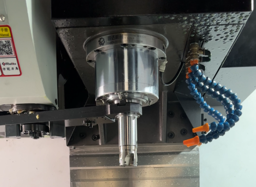
Stop the Machine After These Events
- A tool falls from the spindle or double arm.
- The arm, pocket, holder, or spindle dog appears bent.
- The holder remains partly inserted.
- The spindle dogs strike the holder slots.
- The changer reaches a different position on each cycle.
- Arm-position or cambox-overload alarms repeat.
- A sensor signal appears and disappears during movement.
- The arm moves while a pocket or spindle is not clear.
Inspect fresh metal marks, cracked plastic, bent brackets, moved bolt marks, damaged holder slots, loose fasteners, gripper wear, and pocket damage. Trace the contact marks through the spindle, holder, arm, and magazine instead of changing the closest parameter.
A power loss during a tool change is not automatically a collision. Check for a trapped or unsupported tool and use the machine-specific recovery procedure. Some controls can reset an axis or carousel zero during recovery, so do not change offsets before completing the correct recovery steps.[6]
Tool Falls While Stored in the Magazine
Inspect:
- Pocket fingers
- Retaining springs
- Plastic retaining parts
- Pocket mounting bolts
- Holder flange dimensions
- Tool weight and length
- Oil, coolant, and chips
Place a known-good holder in the failed pocket. Then place the failed holder in another known-good pocket.
- If several holders fall from one pocket, repair that pocket.
- If one holder falls from several pockets, inspect the holder, taper, pull stud, flange, weight, and center of gravity.
- If several nearby pockets fail, inspect the local guide, support, chain section, or carousel plate.
- If every pocket fails at the transfer point, check the magazine index, arm position, and pocket-motion reference.
Use only the holder and pull-stud type specified for the spindle. A damaged taper, wrong pull stud, or debris between the holder and spindle can damage the spindle and interfere with tool changing.[7]
A labeled CNC toolholder storage system helps separate HSK, BT, SK, and CAT holders and prevents mixed pull studs, dirty tapers, damaged holders, and unmarked heavy tools from being returned to the magazine.
Tool Falls While Entering a Pocket
Check whether:
- The pocket reaches its full raised or lowered position.
- The magazine stops at the pocket center.
- The pocket fingers open and close freely.
- The holder flange enters without side contact.
- The position sensor switches before the pocket finishes moving.
- The pocket cylinder loses pressure during movement.
One failed pocket points to local damage. Failure at every pocket points to the overall transfer position, magazine index, or arm alignment.
Tool Falls From the Spindle
A tool that falls before the unclamp command has a serious clamping fault. Check:
- Drawbar force
- Belleville spring condition
- Pull stud or HSK clamping interface
- Retaining balls or HSK clamping segments
- Spindle and holder tapers
- Clamp and unclamp sensors
- Tool-release piston position
A tool that falls after release but before the arm grips it may involve early release, slow arm movement, low air flow, wrong sensor timing, or a release-piston problem.
Measure drawbar force with the correct gauge. Sound, hand feel, and the effort needed to remove a stationary holder are not valid measurements.
The correct force depends on the exact spindle taper, speed, drawbar design, production version, and holder system. Haas states that a loss of about 50% of nominal clamp force can indicate a cracked or broken Belleville spring washer. That figure is a Haas diagnostic indicator, not a universal limit for every spindle.[8]
Compare the measured force with the range and test method for the exact spindle.[9]
After replacing spindle gripping parts, check the spindle pull claw, pull stud, holder, and spindle taper together. A new pull claw cannot correct an incompatible pull stud or damaged holder.
Tool Falls During Arm Rotation
Inspect:
- Gripper fingers
- Gripper springs and plungers
- Arm height and rotation
- Arm clamping bolts
- Holder flange damage
- Cambox timing and bearings
- Tool weight, length, and center of gravity
If the same arm end drops different tools, compare its gripper, spring, plunger, and groove engagement with the opposite end. If both ends lose tools at the same point, check the drive, cambox, timing, and tool load. Double-arm positioning alarms can also come from an obstruction, incorrect spindle orientation, or cambox damage.[10]
Tool weight alone does not describe the arm load. An 8 kg tool with its center of gravity 150 mm from the holder flange creates about 11.8 N·m of static moment:
8 × 9.81 × 0.15 = 11.8 N·m
Moving the same 8 kg center of gravity to 300 mm creates about 23.5 N·m:
8 × 9.81 × 0.30 = 23.5 N·m
The tool still weighs 8 kg, but its static moment has doubled. Arm acceleration adds more load. Long boring heads, face mills, angle heads, and extensions can therefore cause a tool-change fault while remaining below the stated weight limit.
This matters more on machines using large BT50 tools or larger magazines, such as the heavy-duty horizontal machining center, where tool length and center of gravity must be checked with the magazine and spindle limits.
Spindle Dogs Hit the Holder
Check the spindle orientation before changing the arm position.
- The angle is wrong by the same amount: Check the orientation offset and encoder reference.
- The angle changes on each attempt: Check the encoder belt, pulleys, set screws, feedback cable, and spindle drive.
- The fault appears only after high-speed running: Check spindle deceleration, belt grip, heat, motor feedback, and drive control.
Wrong orientation can rotate the holder during insertion, scrape the drive slots, produce a hard knock, leave the holder partly seated, or trigger clamp alarms.
One Classic Haas Control procedure allows an indicator error of no more than 0.010 in, equal to 0.254 mm, for the machines covered by that procedure.[11]
A separate Haas DC-series procedure uses 0.001 in, equal to 0.0254 mm.[12]
The values differ by 10 times because the procedures cover different machines, measuring points, reference axes, and setups. Neither value should be copied to another model.
The Gripper Misses the Holder Groove
Check the Z-axis tool-change height and double-arm height when the gripper enters above or below the holder groove.
Possible causes include:
- Wrong Z-axis tool-change position
- Changed spindle installation height
- Wrong arm height
- Loose arm mounting
- Cambox shaft movement
- Z-axis coupling or brake problems
- Poor axis repeatability
Use a clean master holder or the OEM alignment fixture. A worn production holder can give a false result.
- If both the spindle and magazine sides are high or low, check the complete arm height.
- If only the spindle side is wrong, check the spindle and Z-axis tool-change position.
- If only one pocket is wrong, repair that pocket instead of moving the complete magazine.
Nominal axis travel does not equal available tool-change clearance. On the LJ-855, the 550 mm Z travel must still cover the holder, cutting tool, fixture, workpiece, safe clearance, and tool-change position. The LJ-855 work-envelope data can be used to check how much space remains after the setup is loaded.
One Pocket Is Wrong or Every Pocket Is Wrong
| Error Pattern | Parts to Inspect |
|---|---|
| One pocket is wrong | Pocket body, hinge, mounting, retaining parts, and local damage |
| Several nearby pockets are wrong | Local guide, support, chain section, or carousel plate |
| Every pocket is offset in the same direction | Index zero, sensor position, servo reference, and overall alignment |
| Stopping point changes randomly | Backlash, loose hardware, drive slip, sensor, and feedback |
On a chain magazine, an increasing position error can come from chain stretch, sprocket wear, guide movement, or a wrong servo reference.
On a carousel, a repeating pattern can come from plate runout, hub movement, a bent pocket, or an indexing error.
Chips, spindle-orientation faults, damaged parts, drive faults, and proximity-sensor problems can all cause carousel or shuttle alarms.[13]
The Position Sensor Switches Too Early or Too Late
- No signal: Check the sensor face, target, gap, cable, connector, and control input.
- Early signal: The control sees the position before the mechanism finishes moving.
- Late signal: The mechanism reaches position but waits for confirmation.
- Unstable signal: The switch point changes because of vibration, wiring, coolant, changing pressure, or a loose bracket.
Watch the physical mechanism and the control input at the same time. A sensor should confirm completed movement. Do not move the sensor only to make incomplete travel appear correct.
Tool Release Takes Too Long
On machines with a pneumatic tool-release piston, check:
- Air pressure while the piston moves
- Available air volume
- Filter and regulator condition
- Restricted hoses
- Air leaks
- Solenoid response
- Blocked exhaust mufflers
- Piston seals and travel
- Spindle and holder taper contamination
Low pressure or insufficient air volume can slow the tool change or prevent the spindle from releasing the holder.[14]
Measure pressure during release, not only while the machine is idle. For example, the gauge may show 90 psi at idle but fall to 62 psi during release. The 28 psi drop identifies a supply or flow problem even though the idle reading looks normal. These figures are a diagnostic example; use the pressure range specified for the machine.
A tool that releases with a loud pop may have a dirty holder or spindle taper, a damaged pull stud, dry retaining balls, or incorrect release-piston movement.
The Arm or Pocket Moves Too Slowly
Inspect:
- Rails and rollers
- Bearings and guide blocks
- Chains and sprockets
- Pocket hinges
- Cambox oil and lubrication
- Bent sheet-metal covers
- Chip and coolant buildup
- Servo acceleration and positioning
- Large- or heavy-tool settings
Compare tool-change time only when spindle starting speed, tool weight, pocket distance, air pressure, machine temperature, and program sequence are similar.
If one tool change becomes 0.8 seconds slower and the machine completes 800 changes per shift:
- 0.8 × 800 = 640 seconds per shift
- 640 seconds = about 10.7 minutes per shift
- Across 250 production days = about 44.4 hours
This is a production-loss calculation, not a calibration threshold. Find the slow step before changing any position value.
After a Repair or Parameter Loss
Check mechanical alignment after work on the spindle, arm, cambox, pockets, magazine supports, shuttle rails, rollers, ballscrew, brake, or coupling.
Check the reference position and repeatability after replacing an encoder, servo motor, encoder belt, motor pulley, proximity sensor, sensor target, or feedback cable.
Control work can create three different faults:
- Offset loss: A stored spindle orientation or tool-change position is missing or changed.
- Reference loss: An axis or magazine has lost its zero point.
- Pocket mapping error: The pocket number on the control does not match the physical magazine.
Restore the verified backup from the same machine before creating new values. Do not move a correctly aligned magazine to match an incorrect pocket table. Do not copy parameters from another machine without measuring the actual position.
Use This Ten-Step Diagnostic Order
- Record the alarm, tool, pocket, program line, and failed movement.
- Use a clean, known-good holder with the correct interface.
- Test that holder in several pockets.
- Test several approved holders in the failed pocket.
- Inspect bolts, pockets, grippers, springs, holders, and contact marks.
- Check air pressure, lubrication, drive alarms, and sensor inputs.
- Measure the same position several times under the same conditions.
- Repair loose, worn, pneumatic, electrical, or feedback faults.
- Adjust only the position proven to be wrong.
- Record the old and new measurements and complete a full-speed test.
Do Not Return the Machine After One Successful Change
Start with an empty holder and use recovery, setup, or reduced-speed mode where available. Increase speed only after the holder enters the spindle and pocket without contact.
Test:
- The repaired position
- Several magazine pockets
- Both ends of a double arm
- A light holder
- A normal production holder
- A longer approved holder
- A heavier approved holder
- Cold and normal operating temperatures
Example: five readings before repair may cover a 0.31 mm range, while five readings after repair cover 0.02 mm. The smaller range shows better repeatability, but the average position must still meet the OEM limit.
Production restart requires all of the following:
- Positions remain within the OEM limits.
- Repeated readings stay consistent.
- The spindle dogs do not contact the holder.
- The grippers enter the holder grooves without side load.
- Pockets finish moving before the sensors switch.
- Clamp and unclamp signals remain stable.
- Drawbar force meets the spindle specification.
- Dynamic air pressure remains stable.
- No new contact marks, alarms, or abnormal sounds appear.
Set Inspection Intervals by Tool-Change Count
A toolroom machine completing 50 changes per day reaches about 13,000 changes in 260 working days. A production machine completing 1,000 changes per day reaches 260,000 changes in the same period—20 times more ATC cycles in the same calendar year.
Use tool-change count, tool weight, tool length, coolant exposure, chip contamination, collision history, and alarm history to set inspection intervals. Recalibration itself is not a fixed weekly or monthly maintenance task.
Inspect the changer after a collision, unexplained dropped tool, spindle or ATC repair, encoder replacement, parameter loss, repeated position alarm, machine relocation, or clear change in tool-change sound or time.
Finally
Recalibrate only after repeated readings show the same fixed error in a spindle angle, Z tool-change position, magazine reference, or axis zero. Five readings with a 0.02 mm range indicate a stable position; readings spread across 0.37 mm indicate looseness, wear, feedback, or air-supply trouble. Locate where the tool drops, measure drawbar force, check dynamic air pressure, inspect the arm and pockets, and verify sensor timing before changing parameters. After repair, test several pockets, both arm ends, long and heavy holders, cold and warm operation, and full-speed movement. Record the original values so an incorrect adjustment can be reversed.