

A cutting tool usually wears out quickly because the cutting edge receives too much heat, force, friction, or impact. High cutting speed, incorrect feed, poor chip removal, vibration, runout, weak clamping, and the wrong tool grade are the most common causes.
Do not replace the tool and continue with the same settings. Stop the machine, inspect the worn edge, and identify whether the damage comes from heat, rubbing, impact, material sticking to the edge, or chips trapped in the cut.
This article focuses on metal-cutting tools used for CNC turning, milling, drilling, boring, grooving, and parting.
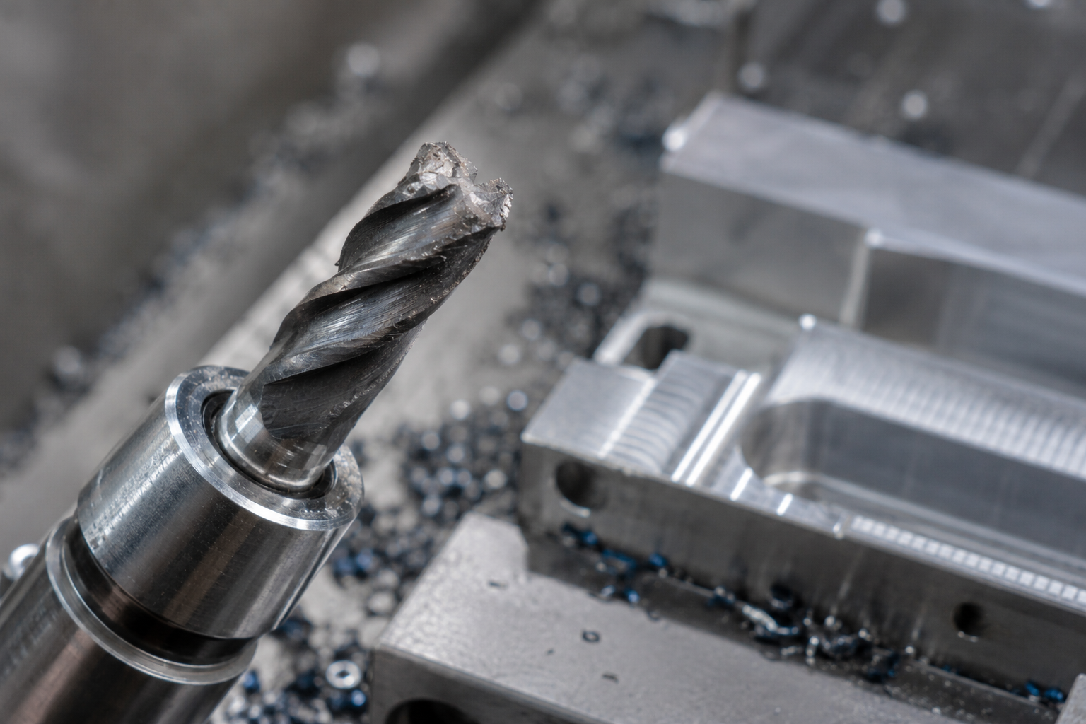
Is the Wear Normal?
All cutting tools wear. Normal wear develops slowly and can be predicted. The tool produces acceptable parts until it reaches the replacement limit set for that operation.
Abnormal wear usually has one or more of these signs:
- The insert chips after only a few parts.
- One flute wears much faster than the others.
- Tool life changes greatly between material batches.
- The edge cracks or breaks without warning.
- Surface finish suddenly becomes rough.
- Part dimensions begin to drift early.
- Spindle load rises faster than usual.
- Burrs become larger after a small number of parts.
- The tool fails at the same point on every workpiece.
Do not judge tool life only by minutes of machining. A tool used for heavy roughing will normally have a shorter running time than a tool used for light finishing. A better measure is the number of acceptable parts produced by each cutting edge.
Record the machine, tool model, insert grade, material batch, cutting speed, feed, cutting depth, coolant condition, number of parts, and final wear pattern. These records help show whether the problem comes from the tool, material, machine, or setup.
Common Wear Patterns
The shape and location of the damage provide useful clues. Inspect the cutting edge with a magnifier, inspection camera, or toolmaker’s microscope after the spindle has stopped completely.
Flank wear appears on the side of the tool that touches the newly machined surface. A narrow, even wear band is usually normal. Fast flank wear can come from high cutting speed, abrasive material, rubbing, hard scale, work hardening, or a tool grade with poor wear resistance.
Crater wear forms on the surface over which the hot chip flows. It often looks like a hollow area behind the cutting edge. High cutting temperature, excessive speed, long chip contact, and an unsuitable tool grade can make crater wear develop faster.
Notch wear appears near the depth-of-cut line. It is common when the edge repeatedly contacts work-hardened material, oxide scale, casting skin, forging skin, or another hard surface layer.
Chipping means small pieces have broken away from the edge. Likely causes include vibration, runout, interrupted cutting, excessive feed, weak edge geometry, chip impact, loose clamping, or poor entry into the workpiece.
Thermal cracks often appear as several narrow cracks across a milling insert. They develop when the edge repeatedly becomes hot in the cut and cools after leaving it. Unstable coolant flow can make this temperature change more severe.
Plastic deformation makes the edge look flattened, rounded, or pushed backward. It means the cutting temperature or load has exceeded the strength of the tool material.
Built-up edge is workpiece material stuck to the cutting edge. The stuck material changes the shape of the tool. When it breaks away, it may pull off the coating or chip the real edge.
Why the Edge Loses Material
Tool wear is not caused by friction alone. Several wear mechanisms can act at the same time.
Abrasive wear happens when hard carbides, casting sand, scale, or hard surface layers scrape the cutting edge. It often causes steady flank wear.
Adhesive wear happens when workpiece material sticks to the tool under high pressure. When the stuck material comes off, it may remove part of the coating or edge.
Diffusion wear develops at high temperatures when elements move between the tool and workpiece at the contact area. It often contributes to crater wear during high-speed continuous cutting.
Oxidation wear occurs when heat and air form a weaker surface layer on the tool. The moving chip then removes this layer.
Fatigue wear comes from repeated cutting forces or temperature changes. Small cracks grow over time until part of the edge breaks away.
Cutting Speed
Cutting speed strongly affects cutting temperature. If it is too high, flank wear, crater wear, coating damage, oxidation, and edge deformation can develop quickly.
RPM is not the same as cutting speed. The same RPM produces a higher cutting speed when the tool or workpiece diameter is larger.
A 100 mm diameter part running at 1,000 RPM has a cutting speed of about 314 m/min:
A 50 mm part at the same RPM has a cutting speed of about 157 m/min. The RPM has not changed, but the cutting speed has been reduced by half.
When the tool has smooth, even, heat-related wear, reduce cutting speed in a small controlled step while staying inside the tool supplier’s recommended range.
Lower speed is not always better. Very low speed can cause workpiece material to stick to the edge, especially when cutting low-carbon steel, stainless steel, or aluminium.
Feed
Feed controls chip thickness and cutting force.
Feed that is too high can overload the cutting edge. It may cause chipping, tool deflection, high spindle load, workpiece movement, rough surfaces, and heavy burrs.
Feed that is too low can also shorten tool life. A cutting edge has a small radius and is not perfectly sharp. If the chip is too thin, the tool presses and rubs the material instead of cutting it cleanly.
Rubbing creates heat, increases flank wear, encourages built-up edge, and can harden the surface of stainless steel and nickel alloys.
For milling, use feed per tooth rather than checking only the table feed:
Assume all four flutes of a cutter are active. At 2,000 RPM and 800 mm/min table feed:
If spindle speed rises to 4,000 RPM while table feed remains at 800 mm/min, the feed falls to 0.05 mm per tooth. The tool may begin rubbing unless the table feed is adjusted.
The same issue appears when the number of flutes changes. At 2,000 RPM and 800 mm/min, changing from a four-flute cutter to an eight-flute cutter reduces feed per tooth from 0.10 mm to 0.05 mm if table feed is not changed. The CNC still displays 800 mm/min, but each edge removes only half as much material.
Small side cuts can also produce thinner chips than expected. Do not raise feed only because a formula suggests it. Check the tool supplier’s data, spindle load, chip shape, cutting sound, and tool wear.
More detailed examples for mold-steel machining are available in the AsiaTools guide to CNC roughing parameters for P20 and H13.
Cutting Depth
Excessive cutting depth increases force and tool engagement. It can cause deflection, chatter, insert breakage, workpiece movement, and dimensional error.
A shallow cut is not automatically safer. Problems occur when the real cutting depth is too small for the cutting edge, remains inside a work-hardened layer, or only touches hard scale.
Machine and tool deflection can also make the actual cutting depth smaller than the programmed value. The tool then rubs instead of cutting.
When machining a casting, forging, flame-cut plate, or work-hardening alloy, use enough depth to cut below the affected surface when the machine, tool, and workholding can support the load.
If notch wear always appears at the same point, changing the depth slightly between passes may spread the wear across a larger part of the edge.
Tool Grade
A tool grade must match the material, cutting temperature, and stability of the operation.
A wear-resistant grade can provide longer life in stable continuous cutting, but it may chip under heavy impact. A tougher grade can handle interrupted cuts and unstable loads, but it may wear faster at high temperature.
Use the wear pattern to guide the choice:
- For smooth and even flank wear, consider greater wear resistance.
- For crater wear or deformation, consider greater heat resistance.
- For chipping in a stable interrupted cut, consider a tougher grade.
- For random breakage, check the setup before changing the grade.
Do not use a tougher insert to hide a loose fixture, damaged holder, blocked chip path, excessive overhang, or high runout. These problems will continue to overload the edge.
For mold-steel applications, see the AsiaTools guide to carbide grades, coatings, and cutting geometry.
Tool Material
High-speed steel has good resistance to impact and can be ground into sharp shapes. It is widely used for drills, taps, reamers, and other tools. Its heat resistance is lower than carbide, so it normally needs a lower cutting speed.
Carbide supports higher speeds and provides good wear resistance. It is widely used for turning inserts, milling cutters, drills, and boring tools. It is more sensitive to impact, runout, and weak clamping than high-speed steel.
Ceramic keeps its hardness at high temperature and can be used for selected cast-iron, hardened-steel, and nickel-alloy operations. It is less tolerant of vibration and impact. A ceramic tool used for a nickel alloy should not automatically be used for titanium.
CBN is commonly used for hard iron-based materials. It needs a rigid machine, low runout, and stable clamping.
PCD is commonly used for non-ferrous metals, high-silicon aluminium, graphite, and abrasive non-metallic materials. It is not a general choice for ordinary steel because chemical wear can develop quickly at cutting temperature.
Common inserts and other products for turning, milling, and drilling can be found in the AsiaTools CNC cutting tools range.
Coating and Edge Shape
Coatings can reduce friction, resist heat, and slow tool wear. The correct coating depends on the workpiece and cutting conditions.
A thick coating can make an edge less sharp. That may increase cutting force during light finishing, aluminium machining, or thin-wall work.
A sharp positive edge cuts with lower force but has less support against impact. It is useful for thin parts, sticky materials, finishing, long overhangs, and low-power machines.
A reinforced edge can carry a heavier load, but it creates more cutting force. It needs a rigid toolholder, machine, and fixture.
The chipbreaker must match the feed and cutting depth. A finishing chipbreaker may not control thick roughing chips. A roughing chipbreaker may not work when the feed is very low.
Edge preparation also affects performance:
- A sharp edge produces low force but has less impact resistance.
- A honed edge is stronger but needs enough chip thickness to avoid rubbing.
- A chamfered edge supports heavier loads but produces more cutting force.
- A wiper edge can improve surface finish but cannot correct vibration or runout.
Nose Radius
A larger turning-insert nose radius provides more edge support and can improve surface finish when the setup is stable and the feed is suitable.
It also increases radial force. On thin walls, long shafts, and long boring bars, that force can bend the workpiece or tool and cause chatter.
A smaller radius reduces radial force but gives the cutting point less support. Surface quality still depends on feed, edge condition, vibration, runout, and material sticking to the tool.
Runout
Runout means a rotating tool does not follow one exact centreline. One cutting edge then removes a thicker chip than the others.
Signs of runout include:
- One flute is badly worn while the others still look usable.
- The surface has a repeating pattern.
- Tool life changes after reinstalling the same tool.
- Hole size changes after replacing a drill or reamer.
- Vibration increases as spindle speed rises.
Check the tool shank, collet, holder, spindle taper, insert seats, screws, and cutter body. Dirt, burrs, wear, incorrect assembly, and a bent tool can all create uneven loading.
Measure runout close to the cutting edge. A holder can look accurate near the spindle but have much more runout at the tool tip.
Vibration
Vibration makes chip thickness and cutting force change repeatedly. It can cause chipped edges, surface waves, abnormal noise, unstable dimensions, and short tool life.
Common causes include:
- Excessive tool overhang
- Long or poorly supported workpieces
- Weak fixtures
- Loose or worn toolholders
- Large cutting engagement
- Worn spindle components
- A spindle speed inside an unstable vibration range
Tool deflection rises quickly as unsupported length increases. Under the same load, doubling tool overhang can increase theoretical deflection to about eight times because deflection is related to the cube of the unsupported length.
Reducing overhang by 20% can reduce theoretical deflection to about 51% of the original value:
This is why shortening a tool by a small amount can improve stability more than a small change in cutting parameters.
Shorten the tool and improve workpiece support before making large parameter changes. Lowering feed does not always stop vibration. Feed that becomes too low may increase rubbing.
Changing spindle speed can move the process away from a vibration range. The better speed may be higher or lower, so make a controlled change and inspect the result.
For a more focused diagnosis, read the AsiaTools article on tool chatter in side milling.
Boring-Bar Overhang
Internal turning is especially sensitive to boring-bar length. A conventional boring bar is commonly kept within about four times its diameter when possible.
For example, a 20 mm diameter bar has a 4×D overhang of about 80 mm:
If the same bar must reach 160 mm, the overhang becomes 8×D. Vibration risk rises sharply, and the process may need a larger-diameter bar, carbide bar, damped bar, lighter cutting engagement, or stronger support.
The 4×D value is a practical reference, not a fixed limit. Tool material, holder design, cutting direction, insert shape, and required surface finish all affect the usable overhang.
Chip Problems
Chips must leave the cutting area. Poor chip control can damage a tool even when the speed and feed are reasonable.
Long chips can wrap around the tool or workpiece, block coolant, scratch the surface, and stop automated production. Check the chipbreaker, feed, speed, and cutting depth.
Packed chips collect inside a hole, slot, flute, or pocket. They can cause a sudden load increase, tool jamming, drill breakage, and severe edge damage.
Recut chips are chips that return to the cutting edge after being removed. They can create random chipping and irregular scratches.
Improve the chip path with suitable coolant direction, through-tool coolant, safe air flow, a different chipbreaker, a suitable drilling cycle, or a revised toolpath.
Horizontal machines can help in work where chips collect around deep pockets or multi-sided parts. The AsiaTools article about horizontal machining centres for mold shops explains how machine layout and fewer setups can improve process stability.
Coolant
Coolant must reach the cutting edge and chip-forming area. Fluid that only hits the holder will not cool or lubricate the contact zone effectively.
Check:
- Nozzle direction
- Flow rate
- Pressure
- Coolant concentration
- Filter condition
- Through-tool passages
- Pump condition
- Foam, floating oil, dirt, or unusual smell
Pressure and flow are not the same. Pressure helps the coolant reach a narrow cutting area and control chips. Flow carries heat and chips away.
Many water-mixed metalworking fluids operate somewhere around 5% to 10%, but the correct value depends on the product and operation. Always follow the coolant supplier’s recommended range and refractometer correction factor.
An 8% concentration in a final 100-litre mixture means about 8 litres of concentrate and 92 litres of water:
It does not mean adding 8 litres of concentrate to a tank that already contains 100 litres of water. That would produce 108 litres of mixture and a lower final percentage than intended.
For water-mixed coolant, use a refractometer and follow the coolant supplier’s correction factor and recommended range. Do not use one concentration setting for every product.
Coolant strategy also depends on the operation. Deep drilling, grooving, aluminium, titanium, and nickel-alloy machining often need reliable coolant for lubrication or chip removal.
Some rough milling operations in steel, cast iron, or hardened steel may perform better dry. Intermittent coolant can repeatedly cool a hot milling edge and increase thermal cracking. Do not remove coolant unless the tool, material, machine, and operation allow dry cutting.
Workpiece Material
Different materials damage cutting tools in different ways.
Low-carbon steel can produce long chips and built-up edge. Harder or heat-treated carbon steel increases cutting force and abrasive wear.
Stainless steel can stick to the tool and become harder when rubbed. A blunt edge, very low feed, shallow repeated cuts, and unnecessary dwell make the problem worse.
Cast iron may contain hard carbides, casting sand, scale, and local hard spots. These can produce fast abrasive wear.
Aluminium often sticks to the cutting edge. Sharp edges, smooth tool surfaces, large chip spaces, and reliable chip removal are important. High-silicon aluminium is more abrasive than low-silicon aluminium.
Titanium keeps heat near the cutting edge. Rubbing, unstable engagement, and poor coolant delivery can shorten tool life quickly.
Nickel alloys remain strong at high temperature, can work-harden, and do not move heat away from the edge easily. They need stable engagement, controlled speed, and reliable coolant delivery.
Hardened steel may require carbide, ceramic, or CBN depending on hardness, interrupted cutting, finish requirements, and machine rigidity.
Material batches with the same general name can still have different hardness, heat treatment, scale, inclusions, or welded areas. If tool life changes suddenly after a new batch arrives, check the material certificate and hardness before changing the CNC program.
Turning Problems
Turning is affected by workpiece diameter, tool height, part support, insert shape, and whether the cut is continuous or interrupted.
When constant surface speed is used, spindle speed rises as the tool approaches the centre. Set a safe maximum RPM to prevent the spindle from exceeding the allowed speed.
Long shafts can bend under radial cutting force. A larger nose radius or stronger negative insert may increase that force.
Internal turning is sensitive to boring-bar length. Shortening the bar or improving support may solve vibration more effectively than changing the insert.
Incorrect tool-centre height can change how the edge cuts, especially on small diameters and during facing near the centre.
Milling Problems
Milling teeth repeatedly enter and leave the workpiece. Each entry creates impact, and each exit allows the edge temperature to change.
Full-slot milling normally places more load on the cutter than light side milling. Tight internal corners also increase the part of the cutter that is in contact with the material.
A cutter may machine straight walls without trouble but chip at the same corner on every part. In this case, check the local cutter engagement and CAM path before slowing the complete program.
Use a controlled entry path and avoid sending the cutter directly into a large amount of material. A curved or rolling entry can load the edge more gradually.
Drilling Problems
Drill life depends heavily on alignment, chip removal, coolant access, and hole depth.
The centre of a drill has very low cutting speed. The chisel edge near the centre pushes material more than it cuts. This is one reason drilling conditions cannot be adjusted in exactly the same way as turning or milling.
If one drill lip wears faster than the other, check runout, holder condition, spindle alignment, entry surface, and drill point geometry.
Deep holes increase the risk of packed chips and blocked coolant passages. A drill can break suddenly when chips fill the flutes.
Excessive peck drilling can add rubbing, repeated re-entry, longer cycle time, and more chances for chips to become trapped. Use a drilling cycle suited to the tool, material, hole depth, and coolant system.
When built-up edge appears on a drill, inspect its location before changing speed. Material sticking near the drill centre may require a different speed change from material sticking near the outer edge.
For mold-base work, see the AsiaTools guide to machining guide-pin, ejector-pin, and cooling holes.
Grooving and Parting
Grooving and parting tools have narrow chip spaces and are sensitive to alignment.
If the blade is not perpendicular to the workpiece, one side rubs against the groove. Excessive extension also makes the blade easier to bend and vibrate.
Coolant must reach the narrow cutting area. Chips that cannot leave the groove may jam against the insert.
Near the end of a parting cut, the remaining material becomes weak and may bend or close around the blade. Check tool height, alignment, workpiece support, and feed near the centre.
Toolholding and Workholding
The cutting tool and workpiece must remain fixed under cutting load.
Check the insert pocket, shim, screw, collet, chuck, arbor, taper, pull stud, boring-bar sleeve, hydraulic holder, and shrink-fit holder.
A small chip under an insert can change its height and angle. A worn insert pocket may allow movement even when a new insert is installed.
On the workpiece side, check jaw contact, clamping force, fixture support, dirt under the part, and the distance between the clamp and cutting area.
Too little clamping force allows movement. Too much force can bend a thin part and cause dimensional error after it is released.
For work that needs fast and repeatable clamping, see the AsiaTools hydraulic clamping system.
Machine Condition
A worn or poorly adjusted machine can shorten tool life even when the tool and program are correct.
Check the spindle bearings, spindle taper, turret alignment, guideways, ballscrew movement, tool-change repeatability, coolant pump, axis movement, and fixture mounting surfaces.
If possible, test the same tool and program on another suitable machine. If the problem appears only on one machine, inspect that machine before making large cutting-data changes.
Routine cleaning, lubrication, taper inspection, and runout checks are covered in the AsiaTools guide to CNC machine maintenance.
How to Find the Cause
Use a fixed checking order instead of changing several settings at once.
- Stop the machine and keep the failed tool.
- Inspect the location and shape of the wear.
- Confirm that the correct tool and insert were installed.
- Clean and inspect the holder, insert pocket, and contact surfaces.
- Measure runout close to the cutting edge.
- Check workpiece clamping and support.
- Check whether chips are wrapping, packing, or being recut.
- Check coolant direction, flow, pressure, and concentration.
- Confirm the actual speed, feed, cutting depth, and cutter engagement.
- Change only one condition.
- Test several edges under the same conditions.
- Compare tool wear, part dimensions, finish, spindle load, and parts per edge.
One insert is not enough to prove that a change works. Material variation, installation error, or random edge damage can make one result misleading.
Quick Diagnosis
| Observed problem | First checks |
|---|---|
| All edges wear evenly | Cutting speed, temperature, material abrasiveness, and tool grade |
| One flute wears first | Runout, insert height, holder condition, and installation |
| Random chipping | Vibration, chip impact, interrupted cutting, and movement |
| Damage at the same part location | Hard spots, scale, cross holes, interrupted surfaces, and toolpath |
| Notch at the depth line | Work hardening and repeated cutting at the same depth |
| Cracks across a milling edge | Temperature changes and coolant stability |
| Tool edge is flattened | Cutting heat, feed, depth, and grade strength |
| Deep-hole tool breaks suddenly | Chip packing, coolant passages, and drilling cycle |
When to Replace the Tool
Do not wait until the tool breaks. Replace it when it reaches the limit set for the operation.
Replacement may be needed when:
- Flank wear reaches the company’s accepted limit.
- Surface roughness exceeds the drawing requirement.
- Part dimensions begin to drift consistently.
- Burr size exceeds the accepted level.
- Spindle load rises outside the normal process range.
- The edge develops cracks or visible chips.
- Chip shape becomes unsafe or difficult to control.
There is no single wear limit for every tool. Roughing, finishing, drilling, grooving, and hard turning need different replacement rules.
A finishing operation may replace a tool when diameter drift reaches 0.01 mm, while another part may allow 0.05 mm. These are examples only. The actual limit must come from the drawing, process capability, and inspection plan.
Tool Cost per Part
Tool cost should be measured by acceptable parts per edge, cycle time, tool-change time, scrap, and rework—not only by purchase price or total cutting time.
Suppose one cutting edge costs $12 and produces 80 acceptable parts:
Another edge costs $18 but produces 150 acceptable parts:
The second insert costs more to buy but has a lower direct tool cost per part. This calculation still does not include cycle time, tool-change labour, machine stoppage, scrap, or rework.
If an unexpected tool failure scraps a $40 workpiece, preventing one failure can save more than the price difference between several inserts. This is why a planned tool-change point is usually better than running every edge until it breaks.
Safety
Stop machining when spindle load rises suddenly, an unusual impact sound appears, the workpiece moves, chips block the cutting area, coolant stops during a coolant-dependent operation, or a tool or clamp appears loose.
- Wait for the spindle and all axes to stop before inspecting the tool.
- Do not bypass machine-door interlocks.
- Do not remove sharp chips with bare hands.
- Use suitable chip-removal tools and eye protection.
- Follow the site’s lockout procedure before entering a hazardous area.
- Do not measure runout while the spindle is powered.
- Avoid using compressed air in a way that spreads sharp chips or coolant mist.
When compressed air is permitted for cleaning, use suitable pressure, eye protection, and a protective device such as a blow-gun chip guarding shield.
Technical References
- Sandvik Coromant: Wear on Cutting Edges
- Sandvik Coromant: Drilling Wear and Troubleshooting
- Sandvik Coromant: Milling Formulas and Definitions
- Sandvik Coromant: Dry Milling or Cutting Fluid
- OSHA: Metalworking Fluid Safety Practices
Conclusion
A cutting tool that wears out quickly normally leaves useful evidence. Even flank wear points toward speed, heat, or abrasive material; one damaged flute points toward runout or poor installation; random chipping points toward vibration, impact, or trapped chips. Check wear, runout, clamping, coolant, feed, speed, and cutting depth in that order. Keep boring-bar overhang near 4×D when possible, measure coolant concentration instead of guessing, and compare tool cost per acceptable part. A stable process should produce repeatable wear, controlled chips, consistent dimensions, and planned tool changes before the edge breaks.