

One deep arc that repeats usually means one insert is cutting lower than the others. Regular lines usually come from feed per revolution and insert geometry. Random scratches usually come from loose chips. Waves with changing cutting noise often point to chatter. A line between passes should be measured before blaming spindle alignment.
| What You See | Check First | Useful Test |
|---|---|---|
| One deep repeating arc | Axial insert runout | Measure every insert at the same radial position |
| Regular, evenly spaced lines | Feed per tooth and feed per revolution | Calculate fz and fn |
| Random scratches | Loose chips | Check whether the marks repeat with cutter rotation |
| Waves with loud cutting noise | Chatter | Change rpm while keeping fz approximately constant |
| Smeared or torn metal | Built-up edge or rubbing | Inspect the cutting edge |
| Marks mainly around holes or slots | Interrupted cutting | Compare marks with workpiece features |
| Visible line between passes | Pass step or different surface lay | Measure the actual height difference |
| One insert wears faster | Unequal load sharing | Check axial and radial runout |
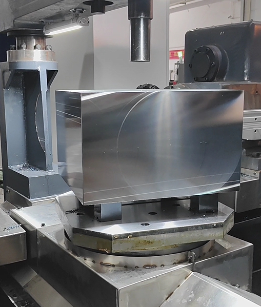
One Deep Arc: Check Insert Height
If one strong arc appears once per cutter revolution, measure the inserts before changing the feed rate.
Small height differences matter:
- 0.005 mm = 5 µm
- 0.010 mm = 10 µm
- 0.020 mm = 20 µm
Suppose five standard inserts are measured from the same reference:
- Insert 1: 0.000 mm
- Insert 2: +0.004 mm
- Insert 3: +0.006 mm
- Insert 4: +0.003 mm
- Insert 5: +0.018 mm
The first four inserts are grouped within 6 µm. Insert 5 reaches another 12 µm beyond that group. It can remove most of the material that determines the final surface.
That can produce three problems at the same time:
- one strong tool mark;
- more cutting load on one insert;
- faster wear on that insert.
Peer-reviewed face-milling research shows that insert mounting errors and axial runout change cutting depth and surface roughness, while radial errors affect how the cutting load is shared between inserts.[3]
A dedicated wiper insert is different. Some cutter designs intentionally place the wiper at a different axial position. Check the cutter specification before trying to make every cutting edge exactly the same height.
Runout After Reseating: Find the Source
Measure the cutter before cleaning it when practical. Then clean and measure again.
- Stop and secure the machine.
- Identify each insert pocket.
- Place a dial test indicator on the same part of every finishing edge.
- Measure every standard insert at the same radial position.
- Record the readings.
- Remove the abnormal insert.
- Clean the insert seat and locating faces.
- Reinstall the insert correctly.
- Measure again at the same point.
Example:
- 0.000 mm
- 0.003 mm
- 0.004 mm
- 0.005 mm
- 0.021 mm
The total spread is:
0.021 - 0.000 = 0.021 mm = 21 µm
The first four inserts sit inside a 5 µm band. The last insert is 16 µm beyond that group.
Use a swap test to find the cause:
| What Happens | Likely Source |
|---|---|
| The abnormal reading follows the insert | Insert |
| The error stays in the same pocket with another insert | Pocket or cutter body |
| All inserts rise and fall together | Cutter mounting, arbor, holder, or spindle |
| Several different cutters show similar error | Toolholder or machine side |
The insert is only the last part of the chain:
spindle → toolholder or arbor → cutter body → pocket → insert
Check mounting faces for chips, dirt, damage, and incorrect seating before changing cutting parameters.
Mixed inserts can also create height errors. Similar-looking inserts may have different thickness, tolerance, edge preparation, or finishing geometry. Check the full specification of the installed CNC cutting tools rather than matching inserts by appearance. A specific SEKN1504AFTN milling insert, for example, should only be replaced with a compatible insert specified for that cutter.
Regular Lines: Calculate Feed Per Tooth
If the marks are regular and similar across the surface, calculate the feed before looking for a mechanical fault.
Vf = n × z × fz
- Vf = table feed
- n = spindle speed
- z = cutting-edge count used for the feed calculation
- fz = feed per tooth
MIT machining material uses the same relationship between spindle speed, tooth count, feed per tooth, and milling feed rate.[4]
For a six-edge cutter running at 1,000 rpm:
| fz | Table Feed |
|---|---|
| 0.05 mm/tooth | 300 mm/min |
| 0.10 mm/tooth | 600 mm/min |
| 0.15 mm/tooth | 900 mm/min |
If rpm and tooth count stay unchanged, doubling fz doubles table feed.
Reducing fz can reduce normal geometric feed marks. It will not correct a dirty insert seat, excessive runout, loose workpiece, or chatter.
Wide Feed Marks: Check Feed Per Revolution
For face finish, calculate how far the cutter moves during one complete revolution:
fn = z × fz
At the same 0.10 mm/tooth:
| Cutting Edges | Feed Per Revolution |
|---|---|
| 4 | 0.40 mm/rev |
| 6 | 0.60 mm/rev |
| 8 | 0.80 mm/rev |
| 12 | 1.20 mm/rev |
A 12-edge cutter moves three times farther per revolution than a four-edge cutter when both use 0.10 mm/tooth.
This matters because the flat finishing part of the insert has a limited width.
For a geometry example, assume a usable finishing land is 2.0 mm wide:
- 0.8 mm/rev gives strong overlap;
- 1.6 mm/rev still gives overlap;
- 2.4 mm/rev moves farther than the example land width during one revolution.
The 2.0 mm value is only an example. Use the actual insert geometry when setting feed.
Wiper Still Leaves Lines: Check Contact
A wiper only works if its finishing edge contacts the surface correctly.
Check:
- wiper axial position;
- standard-insert runout;
- wiper orientation;
- condition of the wiper edge;
- feed per revolution.
A wide wiper can still perform poorly if it is tilted.
For example, an 8 mm-long finishing land does not provide 8 mm of useful finishing contact if only 2 or 3 mm of the edge actually touches the workpiece.
If the surface becomes much better after correcting wiper position but speed and feed stay unchanged, the problem was cutter setup rather than cutting data.
Smearing After Lowering Feed: Check for Rubbing
Lower feed does not always improve finish.
A carbide edge has a real edge radius. When the chip becomes very thin, the insert can rub and push the material instead of cutting it cleanly.
Check for:
- shiny smeared areas;
- extra heat;
- material stuck to the cutting edge;
- poor finish that remains after feed is reduced.
Also check the finishing allowance. A nearly zero-depth finishing pass can rub over the existing surface. An unnecessarily heavy finishing pass creates the opposite problem by increasing cutting force and deflection.
Do not use the smallest possible finishing depth. Use enough stock for the selected edge to form a stable cut.
Smeared Metal on the Edge: Check Built-Up Edge
If workpiece material is visibly stuck to the insert, built-up edge is a stronger suspect than runout.
Built-up edge often follows this pattern:
- material sticks to the cutting edge;
- the temporary edge shape changes;
- surface finish becomes worse;
- the buildup breaks away;
- finish suddenly improves;
- the buildup forms again.
| Finish Change | More Likely Cause |
|---|---|
| Gets worse slowly | Normal wear |
| Changes between good and poor | Built-up edge |
| Becomes poor suddenly and stays poor | Edge chipping |
Inspect the insert before changing speed, feed, coolant, and depth of cut at the same time.
Random Scratches: Get Chips Out of the Cut
Random scratches usually do not come from a single insert height error.
Look for loose chips being:
- dragged across the finished face;
- crushed under the cutter;
- cut again;
- trapped around holes or fixture edges.
If the scratch position changes from one part to the next, chip recutting is more likely than fixed cutter runout.
Check chip collection around:
- holes;
- slots;
- pockets;
- fixtures;
- large horizontal faces.
Where the machine and safety system allow automatic chip clearing, a CNC chip blower can help prevent loose chips from remaining in the cutting area.
Marks Around Holes: Check Interrupted Cutting
If the marks appear mainly beside holes, slots, or casting openings, compare their position with the interrupted features.
Every time an insert leaves the material and enters it again, the cutting load changes.
This can produce:
- edge impact;
- local vibration;
- small edge chips;
- drag marks beside holes;
- different finish in interrupted areas.
If the rest of the surface is clean but marks repeatedly appear after the same holes, changing general insert runout is unlikely to solve the whole problem.
Waves and Noise: Test for Chatter
Chatter becomes more likely when a wavy surface appears together with loud or changing cutting noise and strong sensitivity to spindle speed.
Regenerative chatter can grow because vibration left by one cutting pass changes the chip thickness seen by the next cutting edge.[5]
Test spindle speed without accidentally changing chip load.
For a six-edge cutter at 0.10 mm/tooth:
| Spindle Speed | Table Feed | fz |
|---|---|---|
| 1,500 rpm | 900 mm/min | 0.10 mm/tooth |
| 1,250 rpm | 750 mm/min | 0.10 mm/tooth |
The rpm change is about 16.7%, and table feed is changed by the same percentage.
If rpm falls from 1,500 to 1,000 but feed stays at 900 mm/min:
fz = 900 ÷ (1,000 × 6) = 0.15 mm/tooth
Chip load has increased by 50%. That is no longer a clean rpm test.
If finish changes sharply when rpm changes while fz stays approximately constant, chatter is a stronger suspect.
Do not use this test alone. NIST surface-metrology guidance notes that larger-spaced waviness may be related to machine vibration or chatter, so runout and part movement should also be checked.[6]
Finish Gets Worse Away from Clamps: Support the Part
If finish is good near the clamps but worse in the unsupported area, check workpiece movement before changing inserts.
This is common with:
- thin plates;
- large plates supported only around the edge;
- tall parts;
- parts clamped far from the cutting area.
The plate can bend while the cutter is above it and spring back after the cutting force is removed.
Look for this pattern:
| Observation | More Likely Problem |
|---|---|
| Good finish near support, poor finish farther away | Workpiece flexibility |
| Same chatter everywhere with a long holder | Tool overhang or machine stiffness |
| Short holder works, long holder chatters | Tool overhang |
This large metal plate workholding guide covers the same practical issue: stopping a plate from sliding is not enough if it can still bend under the cutter.
A suitable hydraulic clamping system can improve repeatability, but stronger clamping cannot replace support underneath a flexible workpiece.
Cut Is Unstable: Change Cutter Setup
If the cutter and inserts are mechanically correct but the cut is still unstable, check three setup variables.
| Setup Item | What It Changes |
|---|---|
| Entering angle | Direction of radial and axial cutting force |
| Cutter position | Insert entry, exit, chip thickness, and force direction |
| Cutter pitch | Number of cutting edges loaded at the same time |
A 90-degree cutter sends more cutting force sideways than a smaller entering-angle cutter. A 45-degree cutter splits more of the load between radial and axial directions.
This matters because a thin plate may be weak against axial force, while a long tool assembly may be more sensitive to sideways bending.
Cutter position also matters. If a centered toolpath gives poor exit marks or vibration, test an appropriate offset rather than assuming the cutter must always run exactly on the workpiece centerline.
Pitch should match machine stability and chip space. A close-pitch cutter has more cutting edges available per revolution. A coarse-pitch cutter has fewer edges and more space between them.
Cross Marks or Pass Steps: Check Cutter Plane
A very small angle can produce a measurable height difference across a large face mill.
The geometric relationship is:
height difference = width × tan(tilt angle)
Using an example tilt of only 0.01°:
| Distance | Approximate Height Difference |
|---|---|
| 20 mm | 0.0035 mm = 3.5 µm |
| 100 mm | 0.0175 mm = 17.5 µm |
| 200 mm | 0.0349 mm = 34.9 µm |
The 0.01° value is a geometry example, not an alignment tolerance.
The table shows why the same small angular error becomes easier to see as cutter diameter increases.
If the trailing side of the cutter contacts the surface again, it can leave:
- a second set of arcs;
- cross marks;
- a different surface pattern between passes.
Measure a pass line before adjusting machine geometry.
A visible witness line might measure only 0.003 mm, while another similar-looking line could measure 0.025 mm. Visual contrast does not tell you the actual step height.
One Insert Wears First: Check Load Sharing
If one insert consistently wears faster than the rest, do not replace the full set without checking why.
Compare:
- axial insert height;
- radial runout;
- pocket condition;
- insert type;
- interrupted cutting at that position.
A single insert doing more of the work can produce both poor finish and short insert life.
If the same pocket repeatedly damages new inserts, the pocket or cutter body deserves inspection.
Coolant Does Not Fix the Marks: Match It to the Problem
Use coolant or lubrication to solve a specific problem, not as a general response to poor finish.
NIST identifies friction reduction, heat control, and chip removal as important functions of machining fluids.[7]
| Problem | What to Check |
|---|---|
| Material sticking to edge | Speed, insert geometry, lubrication |
| Loose chips scratching surface | Coolant or air direction and chip evacuation |
| Rapid heat-related wear | Cutting speed, insert grade, coolant strategy |
Do not assume that more coolant automatically produces a better finish.
Visible Marks but Good Dimensions: Measure the Right Thing
Do not reject a surface only because the cutter pattern is easy to see.
ASME B46.1 separates roughness and waviness as different parts of surface texture.[8] ISO 21920-2 defines profile surface-texture terms and parameters used for this type of measurement.[2]
| Requirement | Measure |
|---|---|
| Surface roughness | Specified roughness parameter such as Ra or Rz |
| Overall face shape | Flatness |
| Line between two tool passes | Actual step height |
| Visual appearance | Inspect only after dimensional requirements are confirmed |
A shiny surface can be out of flat. A visible cutter pattern can still meet the drawing.
Use This Test Sequence
- Identify the pattern. Repeating, random, wavy, smeared, or pass-related.
- Measure before cleaning. Record insert height when practical.
- Inspect the cutting edges. Look for wear, chips, and built-up material.
- Clean and reseat suspicious inserts.
- Measure again. Determine whether the error follows the insert or pocket.
- Check the tool stack. Cutter, arbor, holder, spindle.
- Calculate fz and fn.
- Check chips and interrupted features.
- Check tool and workpiece stiffness.
- Check cutter angle, position, pitch, and cutter plane.
- Change one variable and test again.
Example: an 80 mm face mill with six standard inserts leaves one deep arc. Feed is reduced from 900 to 500 mm/min, but the deep arc remains. Insert readings are:
- 0.000 mm
- 0.004 mm
- 0.003 mm
- 0.005 mm
- 0.004 mm
- 0.019 mm
A chip is found under the sixth insert. After cleaning and reseating, its reading falls to 0.005 mm.
The spread falls from 0.019 mm to about 0.005 mm:
0.014 mm improvement = 14 µm = about 74%
The cutter is returned to the original 900 mm/min feed and the deep arc largely disappears. That result points to insert seating rather than feed rate as the root cause.
Finally
A face-milling mark should lead to a measurement. One repeating arc means check insert height; a 0.020 mm difference is already 20 µm and can let one insert control the final surface. Regular lines require fz and fn calculations: six edges at 0.10 mm/tooth give 0.60 mm/rev, while twelve give 1.20 mm/rev. Waves that change strongly with rpm point toward chatter, while random scratches point toward loose chips. Large cutters also expose small alignment errors: a 0.01° angle creates about 17.5 µm of height difference across 100 mm. Measure first, correct the mechanical cause, then adjust cutting data.
Safety: Never measure, clean, or adjust a cutter while it is rotating. OSHA requires guarding against hazards from rotating machine parts and flying material.[9] In U.S. workplaces, compressed air used for cleaning is also covered by OSHA 1910.242(b), including pressure, guarding, and personal-protection requirements.[10]